Continue to Site

Welcome to our site!

Electro Tech is an online community (with over 170,000 members) who enjoy talking about and building electronic circuits, projects and gadgets. To participate you need to register. Registration is free. Click here to register now.

  • Welcome to our site! Electro Tech is an online community (with over 170,000 members) who enjoy talking about and building electronic circuits, projects and gadgets. To participate you need to register. Registration is free. Click here to register now.

Touch circuit sound, led. 555 timer

Status
Not open for further replies.
My current hurdle.
Searching the library for parts.
My relay does not exist in the library. Do I build one and add it?

yes.

I'm assuming you are using through hole components and will be working on a standard 0.100"x 0.100" track grid.

My IC's are in sockets. I dont think that makes a difference.

it will make a difference on how close to other components the IC can be placed.
A socket takes more area. Look at the "prolib" PCB symbol library...DIP8, DIP14

I'm using the discrete library to select caps, diodes, and resistors but I'm not sure if they are physically the right size. Mainly the caps. They are all different sizes.

There are pcb symbols named "DISC04' and "DIOD04" in the discrete library that can be used for all 1/4 resistors and 1N4148 diodes. The pads are spaced 0.400" apart. I typically use 0.200 pad spacing for 0.1u-0.47u caps, but you'll need to check the datasheet for the caps you use.

Try to pick a cap spacing, on 0.100" centers that will work for most (or all) caps in you design.

I'm using "header" to indicate the inputs but some of my pins are 2.54mm apart and others are 5mm. Not sure how to be sure that the pins i've selected are the correct dimensions.

You'll need to choose a part and look at its datasheet. You'll be working with close tolerances, so you'll need to check the footprint on the datasheet against the library footprint you use.

Look at parts available from your supplier, choose one, then find a library part (or make one).

Keep any parts you make in a custom library named, for example, "mylibrary".

Its a good idea to start with a component list, find the real parts, check/make/verify library parts.
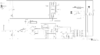
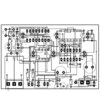
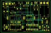
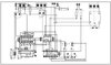
Once thats done, create/update schematic, then create PCB design.

Try to ensure your schematic is correct before starting PCB design, although, as your design progresses, you will make multiple iterations for changes that are made.

Some advice, if you have to make circuit changes, always change the schematic and forward the change to the PCB design (if the PCB design exists). The design process moves more smoothly that way.
 
Last edited:
Some advice, if you have to make circuit changes, always change the schematic and forward the change
Thank you very much. I am making some progress.
You'll need to choose a part and look at its datasheet
These are the connectors (input / output) for power, fan, buzzer, and signal in.

For some reason the "wizard" did not include any of the resistors.

If I replace the 8, 14, and 16 pin IC'S with the sockets will I need to remap all the connections? I assume I make these changes in the pcb and not the schematic.
 
For some reason the "wizard" did not include any of the resistors.

make sure the discrete library is enabled

If I replace the 8, 14, and 16 pin IC'S with the sockets will I need to remap all the connections? I assume I make these changes in the pcb and not the schematic.

Make the change at the schematic. if you don’t like the result you can ctl-z to reverse the change. Then forward the change to the PCB when ready.
It’s a good idea to perform a schematic/PCB check after forwarding a design change to make sure no errors occur.

as long as the pin mappings are the same
(And they should be) it shouldn’t change any connections.
 
Last edited:
Make the change at the schematic. if you don’t like the result you can ctl-z to reverse the change.
My library files do not have sockets or DIP's I do not have a prolib. i have a pcb lib but no DIP's only DIL's. Generic IC's
What I can do is
1) don't place components too close to the IC
2) edit the component and put a 1mm rectangle around it.

Components that did not merge with the PCB wiz were SPLICE. The wiz does not like SPLICE. i changed them to R 0.25W 5% MCF (470k) from the resistor library.

To help with sizing I put a grid on the PCB and set it to 2.5mm. So when i add a component i can see that it is the correct size as the ones i have.
I am having difficulty locating the variable pot.
 
My library files do not have sockets or DIP's I do not have a prolib. i have a pcb lib but no DIP's only DIL's. Generic IC's
What I can do is
1) don't place components too close to the IC
2) edit the component and put a 1mm rectangle around it.

That's ok...as long as you are aware there will be a socket and account for the space when placing parts.

The "prolib" is one of the many libraries that comes with DSPCB, so you probably don't have it enabled.

Components that did not merge with the PCB wiz were SPLICE. The wiz does not like SPLICE. i changed them to R 0.25W 5% MCF (470k) from the resistor library.

Sorry....i don't know what "SPLICE" is.

To help with sizing I put a grid on the PCB and set it to 2.5mm. So when i add a component i can see that it is the correct size as the ones i have.
I am having difficulty locating the variable pot.

Most pin layouts (footprints) on parts are designed to fit on a 0.100 inch grid. So...if you use mm then set the PCB grid to 2.54mm (=0.100 inch). If you don't do this, then pins will be difficult to connect with traces when routing traces on the PCB. I use "inches'" or "mils" but it doesn't matter as long as you manage the grid correctly.
 
The "prolib" is one of the many libraries that comes with DSPCB, so you probably don't have it enabled
If I am in the library manager I can see it but it is not available when selecting components. Ive tried many things. Re-indexing, copy, move, make my own with the wiz. They just won't show.

Ive managed to make the pcb but the resistor available to me is too long. Ive edited it, gave it a new name, saved it. I can see it in the manager but can't access it from the components tab. not sure how to proceed.
 

Attachments

  • TimerPCB.jpg
    TimerPCB.jpg
    196.9 KB · Views: 163
here's how to enable the libraries

Start library manager, then select "Folders" tab

1. Enable folder C:\users\public\documents\DesignSpark PCB 9.0\Library
To enable the folder:
highlight the folder path.
check the "folder enabled" box.
click Apply.

Now you can see all the libraries listed in the lower pane.

2. Enable only the "discrete" and "prolib" library files (to avoid possible part name conflicts).

Library filenames
*.cml = component library <----this contains what is selectable using "add component"
The component library "glues" the schematic symbol and PCB symbol together to form a "component".

*.ssl = schematic symbol library
*.psl = pcb symbol (footprint) library
*.pkg = 3D package library

For each of these libraries enable the files shown below.

For discrete library:
discrete.cml
discrete.ssl
discrete.psl

For prolib library:
prolib.ssl
prolib.psl

Here is how to enable the libraries files.
Highlight the library file name.
Check the "Enabled" box.
click Apply.

Now you can see the parts listed under the different tabs in the library (select the appropriate library with the pulldown menu).
The parts shown in the component tab is what you wil see when you select "add component" in the schematic design of PCB design tool.


Since this is going in the direction of PCB design, I suggest you open a new thread under "PCB design and Simulation" section on this site.
 
I find that from the pcb tab I can alter a component and it applies my changes to all matching items. So I changed the sizes of the resistor from the discrete library and the 3pin trimmer from another. It looks good. The center pin on the trimmer is off by .5mm and the resistor the same. So far the board layout is 85x55mm. Thats just 5mm from my original. I can toy with it and probably get it to 80x50 but its not critical.

Good news. All thoes errors are gone.
I'd like to be sure that the net router did things correctly but that may be difficult.

Cool.

Going forward you should use "Library Loader".
See post #6 here:

 
Files for project with extra circuits removed
 

Attachments

  • ClosetTimerLimited - Project-1.png
    ClosetTimerLimited - Project-1.png
    126.8 KB · Views: 156
  • ClosetTimerLimited - PCB(1)-1.png
    ClosetTimerLimited - PCB(1)-1.png
    258.1 KB · Views: 168
Files for project with extra circuits removed

Did you mean to you uploaded files?
Or review images?

The PCB image is not useful for review.

In the schematic, I noticed the 4013's have active low bubbles on Pre/Clr pins. The 4013's are wired correctly but, for accuracy, the bubbles on the schematic should be removed because the 4013 has active high for those pins. I think there is an exiting schematic symbol "DTYPE03" you can use.
 
you mean to you uploaded files
I removed the external fan/buzzer circuit


I think there is an exiting schematic symbol "DTYPE03" you can use
I do not have that but I did aquire one from Loader. CD4013BEE4.
I removed the auto routing, changed the component, then re ran the auto router. It changed a bit. I think everytime i run that feature the routing is different.
 
I removed the external fan/buzzer circuit


I do not have that but I did aquire one from Loader. CD4013BEE4.
I removed the auto routing, changed the component, then re ran the auto router. It changed a bit. I think everytime i run that feature the routing is different.

You can "fix" a track (lock it in place) so that the router doesn't affect the track.

I never use the autorouter because they never do a good job of routing.:cool:
 
I never use the autorouter because they never do a good job of routing
HERE is my final file. i hope. ive cleaned it up a bunch. the rule checker is upset about overlapping screens but it visually looks ok to me. Can you recommend a developer for this PCB i need 20. 50x80mm
 

Attachments

  • ClosetTimerLimitedPCB.jpg
    ClosetTimerLimitedPCB.jpg
    198.7 KB · Views: 158
Status
Not open for further replies.

Latest threads

New Articles From Microcontroller Tips

Back
Top