Continue to Site

Welcome to our site!

Electro Tech is an online community (with over 170,000 members) who enjoy talking about and building electronic circuits, projects and gadgets. To participate you need to register. Registration is free. Click here to register now.

  • Welcome to our site! Electro Tech is an online community (with over 170,000 members) who enjoy talking about and building electronic circuits, projects and gadgets. To participate you need to register. Registration is free. Click here to register now.

Touch circuit sound, led. 555 timer

Status
Not open for further replies.
The problem I'm having is I think I can somehow attach the timer to the fan circuit in a fashion that the completion of pin 16 would start the timer but I dont see a way to properly trigger the timer with pin 16.
 
Yes. Absolutely

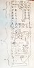
Here is a "delay off timer" circuit that should work (I didn't breadboard it yet).
The relay energizes immediately when any Pin-16 input goes low.
When all Pin-16 inputs then open, the relay will remain energized for the duration of the timer setting. The timer range is approx 30-60 seconds.


1613150347923.png


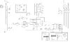
How it works....assume 5v,12v power is applied to the circut.

When all P16 inputs are high:
Q1 is off and Timer is off, so Q3 is off, and therefore, the relay is off.
Q2 is off, therefore, no power is applied to the 555.

When any P16 input goes low:
Q1 turns on and turns on Q3. The relay immediately turn on.
Q3 also turns on Q2. Q2 applies power to the timer, so the timer turns on.
However, the timer does not start because "Tr" is at 5v (C3 is not discharged).

When the last remaining P16 input goes from low to high:
Q1 turns off and would turn off Q3. However, a negative going pulse is generated by
C3 that immediately triggers the timer and keeps Q3 on.
The timer starts and when the time expires, Q3 turn off. The relay deenergizes.
Q3 also turns off Q2 and removes power from the Timer.

The circuit is now reset for the next cycle.

Hope this makes sense. Like I said, I haven't tested this so its still "theory".;)
 
Last edited:
Here is a "delay off timer"
I am simply amazed. I am going to try to figure out how you did this. My parts just came in and I managed to put this voltage reducer together. I will make 3 of these for the three boxes I made that will house the circuit boards. Seven for 2 boxes and 3 for this smaller one. The fan, meter, and speaker will be mounted on these.
 

Attachments

  • 20210212_124614.jpg
    20210212_124614.jpg
    1.2 MB · Views: 153
  • 1613152750483655800055384477993.jpg
    1613152750483655800055384477993.jpg
    982.5 KB · Views: 156
I am simply amazed. I am going to try to figure out how you did this. My parts just came in and I managed to put this voltage reducer together. I will make 3 of

I'll type a circuit description below the schematic in post #222

these for the three boxes I made that will house the circuit boards. Seven for 2 boxes and 3 for this smaller one. The fan, meter, and speaker will be mounted on these.

Nice..
 
Hello,

I've bread boarded and tested the "delay off timer" circuit in post #222.
It works as intended.
 
I've bread boarded and tested the "delay off timer" circuit in post #222.
It works as intended.
I've got to say, that seems a bit of an OTT way of doing that?

How about just a 555 monostable setup, direct from those inputs & output to the relay driver transistor.

Add a diode from the input (pin 2, cathode) to the cap (pins 6 / 7, anode) so it triggers and the output goes high when the input goes low.
But, because the diode prevents the capacitor charging, is does not really start timing until the input goes high again.

eg. Something like this, switch = inputs, output to relay driver transistor base resistor:

retrigerable_555.jpg
 
How it works....
Thank you for the explanation. It makes perfect sense. I'm going to study this until I learn something new.
Q: Q1&Q2 are facing different directions on the schematic. To me they appear to to be flipped for clarity and have nothing to do with how they are connected. Pin 1 on both Q1&Q2 go to +5.
 
Thank you for the explanation. It makes perfect sense. I'm going to study this until I learn something new.
Q: Q1&Q2 are facing different directions on the schematic. To me they appear to to be flipped for clarity and have nothing to do with how they are connected. Pin 1 on both Q1&Q2 go to +5.

If pin 1 is the emitter, yes they both connect to +5.

This may help you understand how a transistor works as a switch.
**broken link removed**
 
Here is a schematic using rjenkingb suggestion. It is a simpler version than #222 and doesn't use Q1/Q2. It still needs Q3.
The difference bewteen the two is #222 uses very little power when not in use. But that isnt too inportant since your using a wall wart for a supply. This should work but should to be tested.

555 Delay Off Timer for FAN-BJT-RJ.PNG
 
Here is a schematic using rjenkingb suggestion.
Thank you. This is exceptional.

I do have a 6 x 28 hole board to work with. It took me some time but i did manage to get all the components for this circuit, the input pins, voltage inputs, output plug & input pins for the speaker all on the same board with just 3 components underneath. (I know Q1&Q2 are not facing the right direction. They won't be when I solder them in.)

I do wish you a Happy Valentines day with your family.
 

Attachments

  • 20210213_135938.jpg
    20210213_135938.jpg
    1.6 MB · Views: 150
My my. I do enjoy this. I just finished, tested, and debuged a completed circuit. Im getting better at wiring while looking at the schematic. I no longer need to have a reversed image to look at. I really need to figure out this pcb design tool. I have a few more to make. It takes me a day to do one.

I do have 2 issues. It beeps when on but no beep when in off state and there is a slight delay when it turns on. Like 1 second. I looked over the board and checked wiring but I just don't see anything so perhaps the observation may help in pointing me in the right direction. I will keep at it in the meantime. Here are some pics.
 

Attachments

  • 20210221_201035.jpg
    20210221_201035.jpg
    838.7 KB · Views: 147
  • 20210221_201027.jpg
    20210221_201027.jpg
    1 MB · Views: 161
  • 20210221_144840.jpg
    20210221_144840.jpg
    2.9 MB · Views: 158
My my. I do enjoy this. I just finished, tested, and debuged a completed circuit. Im getting better at wiring while looking at the schematic. I no longer need to have a reversed image to look at. I really need to figure out this pcb design tool. I have a few more to make. It takes me a day to do one.

I do have 2 issues. It beeps when on but no beep when in off state and there is a slight delay when it turns on. Like 1 second. I looked over the board and checked wiring but I just don't see anything so perhaps the observation may help in pointing me in the right direction. I will keep at it in the meantime. Here are some pics.

Nice.
If you used the PCB design tool, you'd have all the boards done by now . ;)

Its been a while. Please post your current schematic so we can review.
 
Please post your current schematic so we can review.
I was thinking that after i do one the rest would be easier. Nope. Its a spaghetti mess.
I want to make a PCB and have 20 printed. My initial problem is errors in the schematic. I can post whatever you may think may help. Im using Design Spark 9.0
 

Attachments

  • Closet Light Timer-PNG.jpg
    Closet Light Timer-PNG.jpg
    285.2 KB · Views: 156
I was thinking that after i do one the rest would be easier. Nope. Its a spaghetti mess.
I want to make a PCB and have 20 printed. My initial problem is errors in the schematic. I can post whatever you may think may help. Im using Design Spark 9.0

Good choice. I use DesignSpark for all my designs as well and have been using it for a few years. I can help with questions

I suggest you start with ensuring you have all parts you need in the part library first.

If you like, you can PM your design files and I’ll take a look.
 
have all parts you need in the part library first.
My current hurdle.
Searching the library for parts.
My relay does not exist in the library. Do I build one and add it?

My IC's are in sockets. I dont think that makes a difference.

I'm using the discrete library to select caps, diodes, and resistors but I'm not sure if they are physically the right size. Mainly the caps. They are all different sizes.

I'm using "header" to indicate the inputs but some of my pins are 2.54mm apart and others are 5mm. Not sure how to be sure that the pins ive selected are the correct dimensions.
 
Status
Not open for further replies.

Latest threads

New Articles From Microcontroller Tips

Back
Top