Continue to Site

Welcome to our site!

Electro Tech is an online community (with over 170,000 members) who enjoy talking about and building electronic circuits, projects and gadgets. To participate you need to register. Registration is free. Click here to register now.

  • Welcome to our site! Electro Tech is an online community (with over 170,000 members) who enjoy talking about and building electronic circuits, projects and gadgets. To participate you need to register. Registration is free. Click here to register now.

Touch circuit sound, led. 555 timer

Status
Not open for further replies.
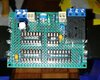
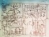
I've made the changes to my schematic. Im going to build this on a new test board. I am curious about a few things...

Does this circuit know the difference between which button is used? Micro / Touch

No...and doesn't care. The input signal, however, must latch on/off.

So this circuit will now ignore a "single" request via (button or touch) to engage relay if a certain condition exists. That condition being that a door is open and the relay off

If that is the case. Then the circuit (after ignoring the request) will reset itself and become ready again.

Sorry..I don't understand the question.

I'm curious how does the circuit know the doors state? Is it voltage based? 5v+ (high) means door closed and 0v (low) means door open?

Again thank you. I am learning a great deal. I like to stay sharp and this is good exercise for me noggin.

It doesn't really know the door state, nor does it really know the relay state. It would take a more complex circuit to include that and act on it.
It is acting on a pulse from the edge detector. First pulse = door open, second pulse = door closed. repeat..

As designed, at power on, the circuit always assumes the door is closed regardless of the state of the input signal.
The first input change following power on will result in a "door open" state.

So when you set this up, you will need to be aware of this and set the actual door state accordingly.

For example, if you have the door open, then power on the circuit, then close the door, the circuit will think the door is open.
The relay will energize, then timeout and de-energize, and the circuit will reset. The next time the door is open the circuit will be synchronized with the door.

We could add a reset button if necessary.
 
Last edited:
For example, if you have the door open, then power on the circuit, then close the door, the circuit will think the door is open.
The relay will energize, then timeout and de-energize, and the circuit will reset. The next time the door is open the circuit will be synchronized with the door.

We could add a reset button if necessary.
Ok i understand. So if the timeout (555) disengages the relay with the door still open nothing will happen when the door is eventually closed. (Lights remain off) and then the circuit is ready for the next latch from the switch/touchpad to turn the lights on again.

But if you closed the door before the timeout the relay will disengage, lights go out, circuit resets, ready for the next latch from the switch/ touch pad to re-enguage the relay and turn the lights on.
:happy:

I need to correct my description.:banghead:

Assumptions:
Door closed.
Pulse from hi-to-low or low-to-hi does not matter. a pulse of either triggers the circuit.

State rules:
ready state=Timer off, Relay off, RED on
open state=Timer on, Relay off, RED off
timeout state= Time expired, Relay off, RED off

1. ready state
2. On Pulse
open state
3. If not timeout
on Pulse Goto 1
Else
timeout state
on Pulse Goto 1 <----waiting for door closed pulse

Now to correct my example with the statements above.
if the door is open when power is applied to the circuit - ready state
But...When the door is then closed - a pulse is generated - open state. <----this is not what you want

The bottom line:
The door has to be closed on power up to match the state of the circuit on power up, unless we manually reset the circuit to the correct state.
Is this going to be a problem?
 
1. ready state
2. On Pulse
open state
3. If not timeout
on Pulse Goto 1
Else
timeout state
on Pulse Goto 1 <----waiting for door closed pulse
This is my language! I understand this. Thats correct and that's perfect.

The door has to be closed on power up to match the state of the circuit on power up, unless we manually reset the circuit to the correct state.
Is this going to be a problem?
Not really but who am I kidding. Its a girls closet. :p it will need a reset. If not for that but for the occasional power outtage.

Ya know i plan on making about 10+ of these. Can they all be powered off the same wallwart. It is 5.2v 1000ma. I will be using a different PS for the actual lights.
 
This is my language! I understand this. Thats correct and that's perfect.


Not really but who am I kidding. Its a girls closet. :p it will need a reset. If not for that but for the occasional power outtage.

:D I know what you mean.

Ya know i plan on making about 10+ of these. Can they all be powered off the same wallwart. It is 5.2v 1000ma. I will be using a different PS for the actual lights.

Each circuit requires about 160mA so if you do the math you'll need 10x160mA=1.6(+0.4A headroom)=2.0A wall wart for 10 circuits
 
You know you got me thinking more about this.

So based on our last comments I came up with new modifications that I think you'll like the best.
It doesn't require any new parts, just some rewiring. And we won't need a reset button.:D

Assumptions:
Door closed=5v
Door open = 0v

State rules:
ready state=Timer off, Relay off, RED on, GRN off, YEL off, door closed
open state=Timer on, Relay on, RED off, GRN on, YEL on, door open
timeout state= Time expired, Relay off, RED off, GRN on, YEL off, door open

Process:
1. ready state
2. On door open
open state
3. If not timeout
On door close Goto 1
Else
timeout state
on door close Goto 1 <----waiting for door to close

Now...for my example with the new statements above:
if the door is open when power is applied to the circuit - timeout state
When the door is then closed - Goto 1

You don't need to worry about reset with this version.
But it does require a latch signal from high-to-low,
where high=door closed, low(or open circuit)=door open

The door-open indicator actually reflects the door status.

This version is working on my bench. :)

See below.

1611718888158.png


Alternate circuit that replaces CD4013 with CD4093B:

1611778541105.png
 
Last edited:
I thought there may be some way of utilizing the voltage to indicate the doors state. :) this is turning out real nice.

Yes. :)

You had mentioned you had a lot of CD4093B chips.
So I've added an optional circuit to post #186 that replaces the CD4013B with a CD4093B.
The functionality of both circuits is identical. Your choice.:cool:
 
Which version did you build?
The 1st version with the 4013 FF.
I'm laying out the chips on a 50x70 PCB. Its going well. I purchased some 28guage coated transformer wire but it was so difficult to scrape the enabled finish off. I now have 26guage bare solid copper.
 
The 1st version with the 4013 FF.
I'm laying out the chips on a 50x70 PCB. Its going well. I purchased some 28guage coated transformer wire but it was so difficult to scrape the enabled finish off. I now have 26guage bare solid copper.

That's alot of work if you going to make 10 of these.
How many are you going to make?
 
18. Ive come this far. I can make 1 per day.

18 Boards. Wow.

You might want to try EasyEDA. I haven't used it but I hear its very good for 1st time users. You could probably learn it within a few days.
The program is online. and even the PCB can be ordered online when finished designing.

Just to give yo an Idea, my recent board purchase from JLCPCB was Qty. 5 for $9. :joyful:
JLCPCB is a chinese fab house but their quality is execellent. The shipping charge cost more than the board. :)

Just a suggestion....
 
And a very welcome one. I will indeed look into it. Thank you.
I did have trouble getting the one I'm using to create the PCB. It was just bunching all the components up on top of one another.

I got curious so I tried EasyEDA.
I just completed one of the schematics using EsayEDA in about 60 minutes, and I never used it before!:)
 
I've laid out the board for both my needs and to reduce wires going all over. Ive also drawn the connections then flipped them so I can make solder connections on the bottom of the board.
About the pcb design software. I have too many questions. I need to work at this a bit more before I ask for help. I have very little understanding of nets and how I keep them in order. I do think this is key to a good pcb design. Becides I'm learning nothing drawing this on paper. Another thing that puzzles me is how do I tell the design software that I have inputs for switches, plugs, jumpers, and terminals? And how does the software know just which adjustable resistor or the type of relay im using? Or that I want to place some components on the other side of the board? Yes. Ive got lots of questions. But I do want to say again. THANK YOU. This was quite the process but it was and still it totally worth all the trouble.
 

Attachments

  • 20210201_222712.jpg
    20210201_222712.jpg
    941.1 KB · Views: 154
  • 20210201_130206.jpg
    20210201_130206.jpg
    1.4 MB · Views: 158
Status
Not open for further replies.

Latest threads

New Articles From Microcontroller Tips

Back
Top