ruzfactor
New Member
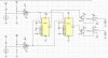
I'm having a problem with MUX in my circuit. It's a strange problem. When I use MM74C151, circuit works as it should be. But when I use SN74LS151 replacing the MM74C151, circuit doesn't work as before. What could be the problem? I don't think there's any problem in SN74LS151 because I have three of those.
Plz help!
Plz help!