Continue to Site

Welcome to our site!

Electro Tech is an online community (with over 170,000 members) who enjoy talking about and building electronic circuits, projects and gadgets. To participate you need to register. Registration is free. Click here to register now.

  • Welcome to our site! Electro Tech is an online community (with over 170,000 members) who enjoy talking about and building electronic circuits, projects and gadgets. To participate you need to register. Registration is free. Click here to register now.

problem while connecting a current transformer

Status
Not open for further replies.

avicreats

New Member
Hello everyone,

*******************This is my first thread.:)

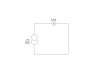
* I have designed a signal conditioning unit(scu) where the input to scu is from current transformer(ct). The problem is that the current from ct when measured with an ammeter shows 0.9amps which was connected as the figure i have attached at first.

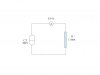
***************** But when i connected the ct input to my scu,the current read by ammeter was 0.6amps.(figure 2).

*************** I thought ct is a constant source to a variable load.Is that right?
I wonder where that 0.3amps has gone.can anyone help me out in this
 

Attachments

  • a.jpg
    a.jpg
    11.8 KB · Views: 208
  • b.jpg
    b.jpg
    13.8 KB · Views: 195
Have you allowed for the ammeter impedance in your setup?
The secondary current (low) of the CT is proportional to the primary current (high). You would normally connect a burden resistor (google that if necessary) across the secondary to develop a voltage which then would be the input to the SCU.
 
the input to scu is from current transformer
Are you using the CT as a source?
Are you feeding the CT from the mains and expecting a constant current output from the secondary?

I thought ct is a constant source to a variable load.Is that right?
I think that maybe you mis-understand the operation and use of a current transformer.

JimB
 
Are you using the CT as a source?
Are you feeding the CT from the mains and expecting a constant current output from the secondary?


JimB

yes,iam using ct as input source..

Yes,expecting a constant current output from the secondary..

and the load i hav connected to ct is a 1ohm resistor..and i got a feel that this 1 ohm resistor makes immatching impedence between primary and secondary?,(max power transfer theorem)..
 
Last edited:
Have you allowed for the ammeter impedance in your setup?
The secondary current (low) of the CT is proportional to the primary current (high). You would normally connect a burden resistor (google that if necessary) across the secondary to develop a voltage which then would be the input to the SCU.
The load connected to the ct is 1ohm resistor,is that a burden issue?..the problem is that i needed an amplification from ct and hence i increased the primary turns...is that a issue that made this problem??
 
Is this current transformer purchased or built? When you say you increased the primary turns is that something you did yourself?
 
i increased the primary turns
Normally for a CT the primary is a single turn (a thick cable carrying high current to be measured). Increasing the number of primary turns reduces the output current in the secondary (which is the winding with many turns). Like JimB, I think you misunderstand the purpose/function of a current transformer.
 
Normally for a CT the primary is a single turn (a thick cable carrying high current to be measured). Increasing the number of primary turns reduces the output current in the secondary (which is the winding with many turns). Like JimB, I think you misunderstand the purpose/function of a current transformer.
I beg to differ. ;) The shorted output current of a current transformer will increase with the number of primary turns. Think about it. If you increased the primary turns to equal the secondary turns, it would be a 1:1 transformer, giving a shorted output current equal to the input current. You just have to make sure that the output load resistor is low enough to keep the burden voltage below its rated value due to the increased current.
 
Last edited:
You're right, crutschow, my bad. I was thinking in voltage terms :eek:.
 
Is this current transformer purchased or built? When you say you increased the primary turns is that something you did yourself?

I hav purchased it,its a split core ct of ratio 50/5. I did a late night work on it with your ideas. For 1amp primary current(with single turn) i received 50 milli amp current on secondary of ct(connected to load).But theoretically i shud hav got (1000*(5/50)) =100 milli amps. Blindly i increased a turn on primary side of ct(totally 2 turns) where i got 100 milli amps on secondary(didnt know how that happened)...
So as alec_t theory was right(burden),then the secondary o/p shoud hav been half of that 50 i.e, 25..But the o/p is relatively maintaining the ratio of 50/5 for 50/10(when increased to two turns)..


Can i hope this to work for the same for even all values of current...So finally ,is there any thumb rule to calculate the secondary current of ct with a load (burden) on sec???:confused:
 
Last edited:
So finally ,is there any thumb rule to calculate the secondary current of ct with a load (burden) on sec?
The secondary current is theoretically the primary current divided by the turns ratio, for various burden resistor values. The resistor value should be such that the VA rating of the transformer is not exceeded.
If the CT is indeed a 50:5 type then 1A through a single-turn primary should give you 100mA secondary current, as you say. I can't explain why you only get 50mA, unless the CT has been wrongly marked and is in fact e.g. a 50:2.5 type.

Edit: What is the VA rating of your CT and what value burden resistor are you using?
 
Status
Not open for further replies.

New Articles From Microcontroller Tips

Back
Top