Continue to Site

Welcome to our site!

Electro Tech is an online community (with over 170,000 members) who enjoy talking about and building electronic circuits, projects and gadgets. To participate you need to register. Registration is free. Click here to register now.

  • Welcome to our site! Electro Tech is an online community (with over 170,000 members) who enjoy talking about and building electronic circuits, projects and gadgets. To participate you need to register. Registration is free. Click here to register now.

Test an AC Current Sensor Transformer

ThomsCircuit

Well-Known Member
I would like to use this to energize a 120vcoil on a relay but I don't know too much about the details of this sensor. Can you help me figure this out and let me know if It can be used to do what I want.

Thanks T.B.

20240421_132232.jpg
 
So, what do you want to do?
I have a 120v power tool. Stationary belt sander. I will run the line from the tool through the sensor. When i apply power to the tool I'd like to use what is generated to trigger a relay coil. From there I could power a vacuum, or other device. Which would remain running as long as the tool is running.

I made something with a smaller current sensor a few years back. With the help from this group of course. It did trigger a relay which then turned on a 5 second delayed On/Off circuit.

sch.png


I want to know would this sensor work like the smaller one in my schematic. Id like to utilize it in the same manner. I'm not sure how interchangeable these are. I'm sure R1 and the zeener change the output from the sensor to DC so that's my ultimate goal.
 
The current transformer in the schematic is 1000:1 ratio.
The one in the photo is 10:1 ratio! It is intended to operate an AC ammeter, not any form of electronics.

(What you have drawn as ZD1 is labelled BAT46 - which is a Schottky rectifier , not a zener.)


The output current from the big CT will be 1/10th the current of whatever load is run through it; they are not voltage devices, they are more like a muzzled tesla coil - without the correct load, the secondary voltage will arc over. They are intended to work into a near short circuit.

You need an appropriate current transducer, suitable for driving electronics.
 
Understood. Thank you for your input. I'll just return this item.
T.B.
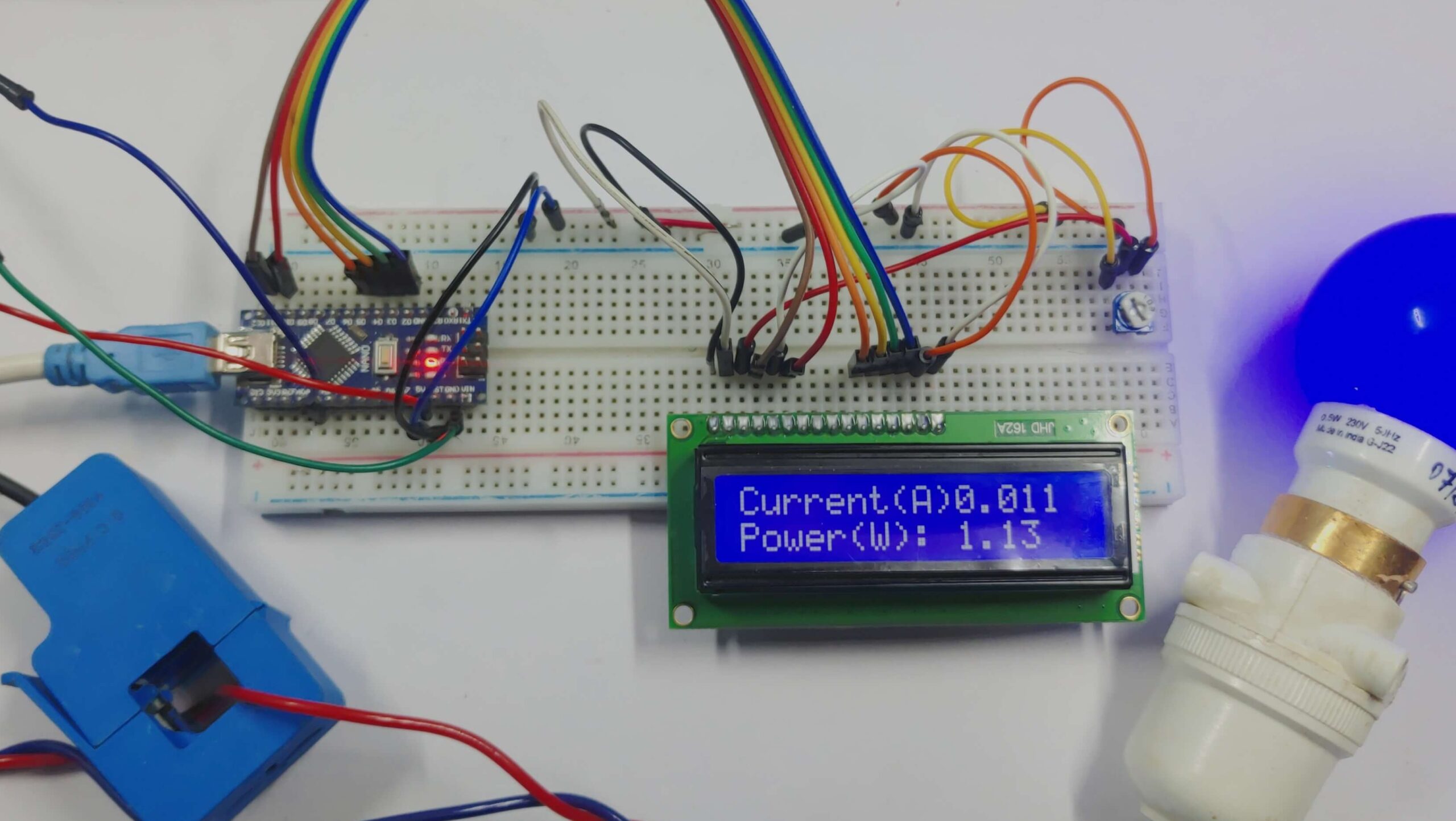
Your one is blue. But the working principle should be as same as the black one used here.
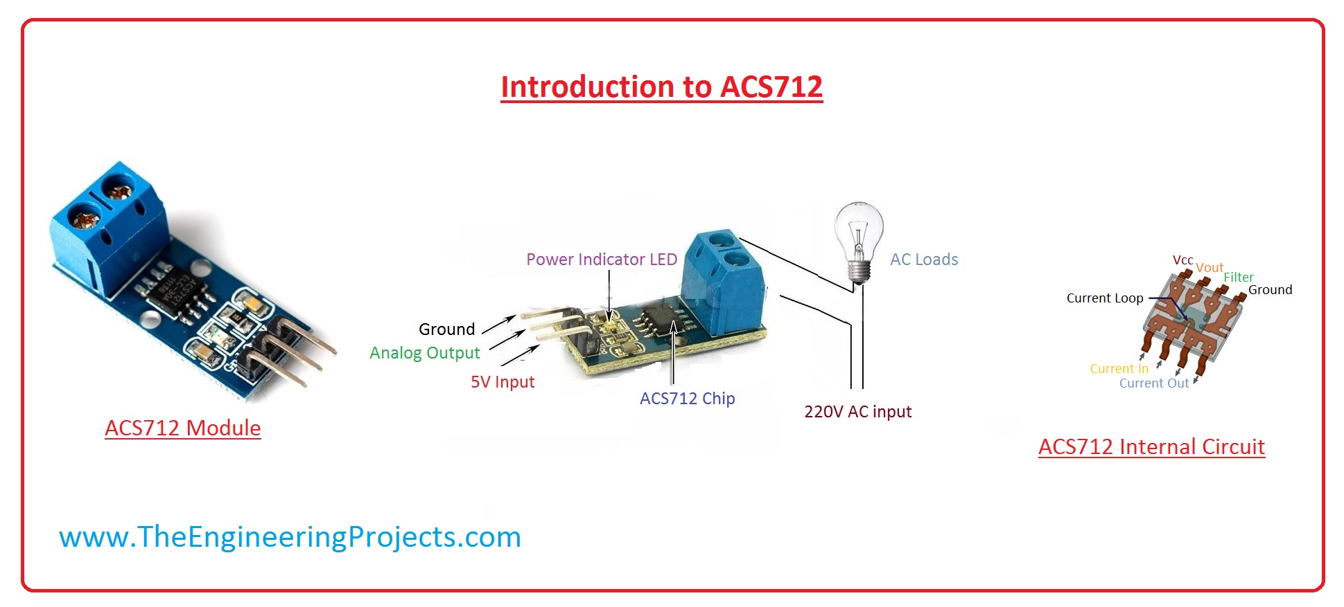
Maybe you have returned this product by this time. I find the ACS712 module more convenient.
ACS712 is an AC or DC current sensor, which is used to measure AC or DC current. The maximum value of AC and DC which can be measured is 30A, its output current signal can be read via analog I/O port of Arduino. It is also available in 5A and 20A version which provides precise and economical solutions for AC or DC current sensing in industrial and commercial systems. ACS712 consists of a precise and low offset linear Hall sensor circuit with a copper conduction path located near the surface of the die. ACS712 is used in different industrial projects and commercial electrical devices which includes motor control switched mode power supplies, load detection, and management and overcurrent fault protection.
 

Latest threads

New Articles From Microcontroller Tips

Back
Top