Continue to Site

Welcome to our site!

Electro Tech is an online community (with over 170,000 members) who enjoy talking about and building electronic circuits, projects and gadgets. To participate you need to register. Registration is free. Click here to register now.

  • Welcome to our site! Electro Tech is an online community (with over 170,000 members) who enjoy talking about and building electronic circuits, projects and gadgets. To participate you need to register. Registration is free. Click here to register now.

what resisitors for these fil. leds??

kåre

New Member
hey!
im looking to wire up a string of these filament LEDs,they are 3v/120mA,3v/300mA,6500k. these are chinesium so please take an extra 5% margin on the safety,so they dont burn out.
that would cut power further down the line,yes?

if i want to make a string of 10 of the 300mA's,that means it needs 3amps @ 3v? so a supply of 3v/3A would be plug and play?
i have a limited assortment of resistors,if its needed. it cant be this easy,right?
what the best bet for an noob like me?

thansk in advance,guys!
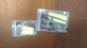
 

Attachments

  • IMG_20240507_120151277.jpg
    IMG_20240507_120151277.jpg
    2.6 MB · Views: 216
They can't be filament and LED, they are completely different things.

If they are LED's, then they are effectively current fed - not voltage fed - so require current limiting resistors, otherwise they take too much current and burn out.

Do you have a multimeter?, if so test them both ways round on the diode test range - if they are LED's then they should read one way (about 2.8V or something) and read over-range (just like with nothing connected) the other way. If they are filament lamps, then they will read the same both ways round.

So try that for a start.
they read OL both ways. and when i try to test the A,it shuts down my bench supply,both ways.
and i know they are of some kinda glass material,they break easily!

so,what do i do now? i got a lot of all kinds of stuff i once thought id need,old radios,resistors,connectors and all kinds of stuff. is there a possibility that a messy home gamer would have something usable lying around?
i have some small step down/up buck converters,too. im very ignorant but willing to learn simple stuff. and i take precautions,always.
and yes,a few multimeters. i obviously dont know how to use them very well,but im careful.
so. please help me mcgyver this thing! i have wires and all!
(did i get this wrong? i did,didnt i?)
thanks,
 
Last edited:
and thanks for letting me know these are NOT LEDs! but i heard that they may be diodes attached to a substrate,glass. but that might not make much sense.
 
They can't be filament and LED, they are completely different things.

If they are LED's, then they are effectively current fed - not voltage fed - so require current limiting resistors, otherwise they take too much current and burn out.

Do you have a multimeter?, if so test them both ways round on the diode test range - if they are LED's then they should read one way (about 2.8V or something) and read over-range (just like with nothing connected) the other way. If they are filament lamps, then they will read the same both ways round.

So try that for a start.
these are useless,right? the 300 bag.
 
My suggestion is to put a 1 kOhm resistor in series with one of the LED sticks and see what happens on a 12 V power supply.
These filaments are LEDs (really who said otherwise) which have a blue substrate and phosphor to radiate very warm white and so have a threshold voltage around 2.7V but are very high resistance. Unlike 5mm LEDs which have Rs around 12 ~15 ohms these depend on length are around 20k ohms each. Thus 43 V @ ~ ? mA is what I think Clive was measuring. What he aces in demonstration entertainment also lacks in engineering theory.

If my hunch is correct ( never tried testing one) (12V - 2.7) / (1k + 20k) should yield about 1/2 mA which is barely visible.

This might show up as "open" on a DMM due to the R scale being too low a voltage and the Diode test scale being too low a voltage at constant current thus exceeding 1.99V shown as blank.

But you can eliminate the resistor and use a higher voltage as long as to avoid the wrong polarity as > -5V can weaken or damage the junction. e.g. 12Vdc thru a mA current meter.

Then after you compute the effective impedance , do the same for a "capacitance dropper" to compute impedance to control the average current to a few mA max. The shunt DC cap should be about 100x the series cap , e.g. 47 nF >= 600V and 47 uF >=160V to attenuate the flicker and also give a realistic delayed turn on time of RC=Tau to for the LED filament to simulate a "tungsten filament". (not all filaments are the same Nigel.)

For those who wish to compare, I suggest 30 mW per filament = V*I then increase according to thermal rise which affects MTBF. It should not exceed 50'C or burn your finger for the so-called fake 50khr MTBF that you often see.
 
Last edited:
Although Wiki is not always 100% such as the unspecified wide current range for Vf of Blue/Wht LEDs , it does support my comments.

They call these White LEDs "3V" because after the threshold voltage is reached and then "some" current voltage drop from bulk series resistance, it ends up being around 3V. Poor quality old 5mm LEDs used to be around >=3.6V @ 20mA rather than 3.1V. That was due to the excess bulk resistance. (lower Vf @ Imax is better and higher efficiency)

I could use more technical language if desired.

Samples
Run each filament at low power to reduce thermal rise limited by lack of conduction or convection cooling.
 
These filaments are LEDs (really who said otherwise)
Someone cannot understand that one can design a ribbon of LEDs and, since they are used as a mock filaments in old-time looking Edison Glow Bulb, many people call these things filaments. And the confusion seems to has started with this definitive, yet misguided, claim.
They can't be filament and LED, they are completely different things.
 

Someone demonstrated these "nOOds" (which are completely different than the filaments being discussed here) at a maker event. They were blindingly bright, and drawing several hundred milliamps.....

The guy had neglected to read the recommendation at Adafruit:

"As the LEDs are in parallel, if you were to power them directly from 3V they can draw up to 200mA - however, like other LEDs it's not recommended to drive them in 'voltage' mode. We recommend current limiting with a resistor to let max 50mA...."

The nOOds are pretty cool, extremely flexible, with a bend radius of half an inch or less. They are available in an abundance of colors. Here's a screenshot from a video at Adafruit.


Screenshot_20240508_125248_Edge.jpg
 
Someone demonstrated these "nOOds" (which are completely different than the filaments being discussed here) at a maker event. They were blindingly bright, and drawing several hundred milliamps.....

The guy had neglected to read the recommendation at Adafruit:

"As the LEDs are in parallel, if you were to power them directly from 3V they can draw up to 200mA - however, like other LEDs it's not recommended to drive them in 'voltage' mode. We recommend current limiting with a resistor to let max 50mA...."

The nOOds are pretty cool, extremely flexible, with a bend radius of half an inch or less. They are available in an abundance of colors. Here's a screenshot from a video at Adafruit.


View attachment 145673
Thanks for reiterating the instructions and images from the link I posted.
 
Thanks for reiterating the instructions and images from the link I posted.

I am soooo sorry. I didn't realize sharing my hands-on personal experience would cause you soooo much duress.
 

Latest threads

New Articles From Microcontroller Tips

Back
Top