Continue to Site

Welcome to our site!

Electro Tech is an online community (with over 170,000 members) who enjoy talking about and building electronic circuits, projects and gadgets. To participate you need to register. Registration is free. Click here to register now.

  • Welcome to our site! Electro Tech is an online community (with over 170,000 members) who enjoy talking about and building electronic circuits, projects and gadgets. To participate you need to register. Registration is free. Click here to register now.

Finding unknown voltage of a transformer

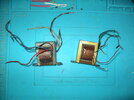
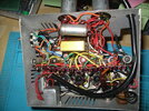
With reference to finding an unknown voltage of a transformer, the advice I have been given is to connect the primary to power etc, BUT how do I know what amount of power to put on, when its an unknown voltage? I don't want to blow the transformer by putting too much through, and how would that tell me anyway that its the right amount of power/ Advice appreciated please? by the way these are small transformers recovered from an old projector amp, not a main power transformer.
 
Measure primary and second L of coil and DCR's

1st order thought logic (?)

Lp/Ls = N turns ratio.
2pi*f*Lp = X(f)= 100x DCR Excitation power @ no load = 10% rated power.
Vin/I(f) = 10x DCR or 10% V drop at rated load.
Rated power efficiency = 90%
Max input power = Vin^2/DCR @ 10% heat loss.
 
by the way these are small transformers recovered from an old projector amp, not a main power transformer.
There is a possibility that they are not mains transformers.

Some clear pictures would be a good start in identifying what they are.
Maybe include a rule in the picture so that we can get an idea of the size of the transformer.

JimB
 
Including a picture of the original amp with the transformers in place would be an even better idea :D

However, assuming it's a valve amplifier?, then it could well have one mains transformer, one output transformer, and one smoothing choke.
 
Measuring the resistance of each coil and the R/L ratio for it's size will tell me exactly what voltage it can handle at 50/60 Hz.
 
1. measure the DCR of each coil.
2. Apply 1vrms to the coil with the highest DCR.
3. (carefully) Measure the RMS voltage across the other coil.

The measurements will reflect the turns ratio.
 
reference my unknown voltage question, photos attached. The amplifier is from an old Ampro 16mm projector, the second photo is of two similar transformers rescued from other old Ampro amplifiers. I hope this helps. Thanks
 

Attachments

  • IMGP0101.JPG
    IMGP0101.JPG
    1.3 MB · Views: 58
  • IMGP0100.JPG
    IMGP0100.JPG
    1.3 MB · Views: 58
Well it's a valve amplifier, so will have a mains transformer, and an output transformer - the mains transformer will have one or two wires feeding the rectifier (presumably one of the valves?), one wire for half wave, two wires for full wave, a third wire will go to chassis - it will also likely have a heater winding which feeds all the valves via twisted wires.

The output transformer will have wires going to the anodes of two of the other valves (the push pull output valves), and a third wire going to the main HT rail. There will be a low resistance secondary, probably with multiple taps, for feeding the speaker.

Can you list the numbers off the valves, and we can tell which is rectifier, and which is the output.
 
Okay, the valves are;
6BR7. 12AX7 35L6GT 35L6GT. 50C5. Oh and the mains transformer is in the body of the projector.
Cheers
 

Attachments

  • Ampro Amp 3a.jpg
    Ampro Amp 3a.jpg
    1.4 MB · Views: 56
Last edited:
Okay, the valves are;
6BR7. 12AX7 35L6GT 35L6GT. 50C5
Cheers

OK, the two 35L6GT valves will be the beam-tetrode push-pull output valves, and their anodes (pin 3) will both directly to the primary winding of the output transformer. A 12AX7 is a standard double triode, a 6BR7 is a small pentode intended for RF/IF use, and a 50C5 is a pentode power valve - I'm not really sure what that's doing there?.

None of them are a rectifier though, so does it use silicon rectifiers, or a metal (selenium) rectifier?.

There's a strange looking silver device on the RHS, about two thirds of the way up, labelled RS1?? -RS1 is all you can see, could that perhaps be a rectifier diode?.

All those valves by the way have 150mA series heaters, so will be wired in series, consisting of 6.3v, 12.6v, 35v, 35v and 50v, giving 138.9V in total. So there needs to be a 138.9V supply (possibly a transformer winding) to power that.
 
As you say in post #1 these transformers are NOT the power supply transformer so they must be transformers in the audio path. ( They are NOT suitable to use as power transformers.)
** IF ** they are from the amplifier shown in post #10 THEN L3 performs the function of a phase splitter and impedance matching between the single ended driver stage and the push pull output stage.
L5 is the output transformer whic performs the function of impedance matching beteen the push pull output stage and the loudspeaker. The only yhing you could use these transformers for is to build a copy of the amplifier that they were removed from.
L2 is used as an oscillator transformer to provide a high frequency variable voltage to the exciter lamp.
I suggest that you dispose of these transformers as scrap metal.

Les.
 
The circuit diagram shown in post #10, does not represent the amplifier shown in post #8.

I believe that these transformers are audio transformers, and so are unsuitable for use in a power supply.

JimB
 
Thank you gentlemen, your advice as always is an eye opener for me, so as I thought, the two little transformers are of no further use. The info on the other aspects is brilliant. I am learning!
 

Latest threads

New Articles From Microcontroller Tips

Back
Top