Continue to Site

Welcome to our site!

Electro Tech is an online community (with over 170,000 members) who enjoy talking about and building electronic circuits, projects and gadgets. To participate you need to register. Registration is free. Click here to register now.

  • Welcome to our site! Electro Tech is an online community (with over 170,000 members) who enjoy talking about and building electronic circuits, projects and gadgets. To participate you need to register. Registration is free. Click here to register now.

My first class AB amplifier

Status
Not open for further replies.

ben7

Member
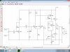
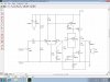
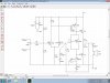
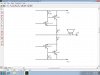
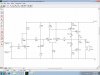
Well after extensive research on class AB amps I have finally built my first one! :0 I just had a spare pair of TIP31/TIP32 transistors that I have used in the circuit. Power supply was 12v @1A, and this amp can drive a 10watt speaker easily! Two medium-sized heat sinks were used, and after a long time at full volume they got just a tad warm. I am looking for feedback on any adjustments to make it better. :)
 

Attachments

  • MyFirstClassABamplifier1.jpg
    MyFirstClassABamplifier1.jpg
    161.7 KB · Views: 1,135
Last edited:
If your amplifier had no voltage losses (it has many) then its output voltage will be 12V peak-to-peak which is 4.24V RMS. Then its output power into 8 ohms is 4.24V squared divided by 8 ohms= 2.25W RMS. But its voltage losses reduce the output power to only 0.5W RMS if the output transistors have gain higher than typical.

The output transistors need a typical base current of 5mA when the peak signal in the 8 ohm speaker is 4V (500mA). But the value of R4 is too high at 2200 ohns so it will have a voltage loss of 11V. Use 200 ohms for a voltage loss of only 1V and if the gain of the output transistors is typical or better.

Another way to reduce voltage losses is to add a bootstrap capacitor to the junction of two resistor R4 in series. Research it.

The two diodes probably do not match the Vbe of the output transistors and will cause crossover distortion or very high idle current and high heating. The two diodes should be replaced by an adjustable Vbe-multiplier transistor. Research it.
 
There's also no gain in the power amp - I would suggest looking at a real circuit and comparing it, this looks like an attempt without understanding why the missing parts make it so poor.
 
The output transistors need a typical base current of 5mA when the peak signal in the 8 ohm speaker is 4V (500mA). But the value of R4 is too high at 2200 ohns so it will have a voltage loss of 11V. Use 200 ohms for a voltage loss of only 1V and if the gain of the output transistors is typical or better.

Ok I see, I will try it with R4 as 220ohms. Yes I aslo know that you can use a capacitor with R4.

The two diodes probably do not match the Vbe of the output transistors and will cause crossover distortion or very high idle current and high heating. The two diodes should be replaced by an adjustable Vbe-multiplier transistor. Research it.

Yes i have seen amplifier circuits with those instead of the 2 diodes.

I will try these changes and see if it makes an improvement.

Also, you didn't notice that it should have a 100pF capacitor between the base and collector on the PNP transistor Q3. ;)
 
Ok I see, I will try it with R4 as 220ohms.
Then remove R3 because it reduces the open-loop gain too much.

Also, you didn't notice that it should have a 100pF capacitor between the base and collector on the PNP transistor Q3. ;)
The open-loop voltage gain of your circuit is so low that it probably will not oscillate without the capacitor. If R3 is removed, R4 is bootstrapped and the differential amplifier has much more gain then the 100pF (or 47pF) capacitor will prevent oscillation when negative feedback is added.
 
I removed R3, and I boot-strapped R4 with 2 100ohm resistors and a 220uF capacitor. Also used a vbe-multiplier as well.

It sounds good!

I think it is oscillating now because when I remove R7, the volume of the music decreases dramatically.

Do you think I should add another pre-amp stage also?

And what about using a dual rail supply?
 

Attachments

  • MyFirstClassABamplifier2.jpg
    MyFirstClassABamplifier2.jpg
    170 KB · Views: 638
Last edited:
I removed R3, and I boot-strapped R4 with 2 100ohm resistors and a 220uF capacitor. Also used a vbe-multiplier as well.

It sounds good!

I think it is oscillating now because when I remove R7, the volume of the music decreases dramatically.

Do you think I should add another pre-amp stage also?

And what about using a dual rail supply?

It's getting closer to been an amplifer now.

1) Add a resistor and capacitor in series from the LH end of R7 down to chassis try a 470 ohm and a 100uF or so for a start, this will give the amplifier some AC gain (set by R7 and the new resistor).

2) Dump the silly preset at the front, and just use two 47K resistors as a potential divider.

3) Use a preset resistor in the Vbe multiplier so you can adjust the bias.

4) Dump the preamp entirely, the power amp should give enough gain to accept line levels - but without the correction in 1) it has no gain at all.
 
It is looking-and sounding-nice now! :)

So what would I have to do to make it have more output watts? Change R7 and/or R9?

I got rid of the "pre-amp" and made the bias adjustable. I added R9 and C3 and that increased the AC gain.
 

Attachments

  • MyFirstClassABamplifier3.jpg
    MyFirstClassABamplifier3.jpg
    168 KB · Views: 475
Last edited:
So what would I have to do to make it have more output watts? Change R7 and R9?
No.
R7 and R9 adjust the voltage gain (sensitivity) that has nothing to do with the max output power.
What makes power? The voltage times the current. The power is increased if the supply voltage is increased because then the voltage and the current are both increased.
Ordinary "low power" car amplifiers use a 4 ohm speaker so the current is pretty high then use two amplifiers in a bridge for each speaker so the voltage is pretty high across each speaker, then the current is also pretty high. My car has 2 ohm speakers and bridged amplifiers.
 
Ah, I knew that.:rolleyes:

Can I get rid of the capacitor on the output?

No, it's absolutely essential - removing it will kill the speaker and the amp.

One obvious improvement, turn the volume control round, that's an absolutely horrible way to connect a volume control, and I hate it! :D

BTW, the maximum power to 8 ohms from 12V is only about 2W, but losses in the amp will lower that further.
 
BTW, the maximum power to 8 ohms from 12V is only about 2W, but losses in the amp will lower that further.

If I changed the power source to 24volts, will that make it louder?

One obvious improvement, turn the volume control round, that's an absolutely horrible way to connect a volume control, and I hate it! :D

lol ok I will change the circuit.
 
Can I get rid of the capacitor on the output?

Now, the (+) terminal of the output capacitor is at half the supply voltage. If you get rid of the output capacitor then there will be a high continuous DC current in the speaker which might melt the speaker and might overheat the amplifier.

But if the amplifier uses a dual polarity supply then without the output capacitor the speaker will have 0VDC so it will work fine.
 
One obvious improvement, turn the volume control round, that's an absolutely horrible way to connect a volume control, and I hate it!

Yep, it shorts the input signal.:p

Also, if I were to change the output transistors to darlingtons, would this make the amp louder? I assume that it will increase current gain.

But if the amplifier uses a dual polarity supply then without the output capacitor the speaker will have 0VDC so it will work fine.

Neat. Maybe I will use a dual polarity +12v -12volt power supply.

Yes, 24V will give you about 8W - same as two bridged amplifiers on 12V will.

Yes, I am familiar with bridging audio amplifiers, you can do that with the LM386 and get twice the output power.

Changed circuit:
 

Attachments

  • MyFirstClassABamplifier4.jpg
    MyFirstClassABamplifier4.jpg
    166.6 KB · Views: 567
Last edited:
I just used it with a dual polarity power supply, I took note that the amplifier is quite sensitive to noisy voltage rails. ;)

It got two times louder, R4 and R4 (yes, my mistake on the circuit diagram) were burning hot, along with Q7 and Q3. :O

I removed the output capacitor and turned it on...no smoke, and music came from the speakers. :)

If you get rid of the output capacitor then there will be a high continuous DC current in the speaker which might melt the speaker and might overheat the amplifier.

My power supply is fused, so that wouldn't happen!
Overheat?! You mean, melt a hole in the transistors!!!
 
Last edited:
if I were to change the output transistors to darlingtons, would this make the amp louder? I assume that it will increase current gain.
A darlington transistor has more saturation voltage loss than an ordinary transistor so the amplifier will have less output power.
The typical saturation voltage loss of a TIP31 ordinary transistor is 0.8V and is 1.4V for a TIP110 darlington transistor. The PNP losses are similar so with darlingtons you typically lose a total of 1.2V which is a lot when the supply is only 12V.

More current gain does not make an amp louder. It simply allows the design to be changed so the driver transistor conducts less current so it is cooler.

I am familiar with bridging audio amplifiers, you can do that with the LM386 and get twice the output power.
Not good enough.
A little LM386 has a small amount of output current. When two are bridged then the current is trying to be doubled which is too high for the little amps so the output power is doubled instead of quadrupled like with more powerful amps.
One LM386 produces 450mW into 8 ohms at clipping with a 9V supply. Its heating is 0.5W.
Two bridged LM386 amps produce 545mW which is only slightly louder than 450mW. Each one heats with 1W. So kiss the battery good-bye.

I just used it with a dual polarity power supply..... It got two times louder, The two R4s were burning hot, along with Q7 and Q3.
Your hearing's sensitivity is logarithmic so you need 10 times the power to be twice as loud. You didn't get 10 times the power.
Twice the supply voltage doubles the voltage and doubles the current in most parts so of course the resistors get 4 times hotter.
Each R4 dissipates 0.34W when the supply is plus and minus 12V. Q3 dissipates 0.68W which is more than its max allowed heating.
Q7 should not get hot because it has a low voltage across it.

My power supply is fused
The fuse protects the power supply from catching on fire. The speaker can still easily burn out and the amplifier can easily overheat without blowing the fuse. When a transistor overheats then it melts inside and is destroyed. No hole.
 
Remember this: When a bipolar transistor overheats it conducts more and when it conducts more it overheats.

Collorary: The transistor will fail to protect the fuse.
 
More current gain does not make an amp louder

So the main idea of building amplifiers is to increase the AC voltage gain?

My new Q3 is a 2SA473, it was one of the few PNP power transistors I had around.

I have seen this output arrangement before, I think it will increase the voltage gain, but I am not sure.
Take a look:
 

Attachments

  • AmplifierOutputStage1.jpg
    AmplifierOutputStage1.jpg
    124.2 KB · Views: 583
Last edited:
Status
Not open for further replies.

New Articles From Microcontroller Tips

Back
Top