Continue to Site

Welcome to our site!

Electro Tech is an online community (with over 170,000 members) who enjoy talking about and building electronic circuits, projects and gadgets. To participate you need to register. Registration is free. Click here to register now.

  • Welcome to our site! Electro Tech is an online community (with over 170,000 members) who enjoy talking about and building electronic circuits, projects and gadgets. To participate you need to register. Registration is free. Click here to register now.

Rookie needs help to understand why his A-class amplifier doesnt work (measurements and schematic attached)

GreenGecko7

New Member
Dear all, nice to meet you !

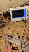
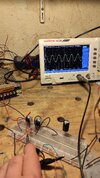
I recently invested in some tools to build amplifiers (my first oscilloscope + all-rounder C and R kits.). My end goal is to build an AM radio.
I have some basic knowledge in electronics : I have studied transistors and OP Amp functioning during my college masters degree. I also have a few Arduino projects under my belt.

However my 2 last tries at building a functiuning Class A amplifier failed. I need some help to understand why !
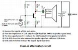
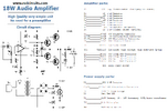
I based the diagram on this famous video :
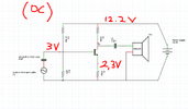
And I adapted the values to fit my 12.2V switch-mode power supply.

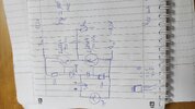
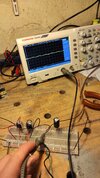
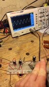
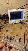
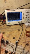
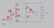
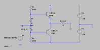
Attached the schematic, in red are the DC measurements made via oscilloscope/multimeter.
Also, no AC component survives the first capacitor : the oscilloscope probing remains flat at +3V DC (DC coupling) when probed on the transistor base with reference on the ground.

Can you help me understand what fails, and suggest me fixes?
I can probe additionnal points if you tell me what to look for specifically.

Thanks a lot in advance ! :)

Benjamin, from France
 

Attachments

  • Circuit class A as made with measurements.PNG
    Circuit class A as made with measurements.PNG
    104.8 KB · Views: 93
Here are some details about your class-A audio amplifier:
 

Attachments

  • class-A transistor.png
    class-A transistor.png
    71.8 KB · Views: 73
  • class-A transistor simulations.png
    class-A transistor simulations.png
    58.4 KB · Views: 62
Can you help me understand what fails, and suggest me fixes?
Just to emphasize what others have said,
the little class A amplifier has an output impedance of about 470 Ohm, if you try to drive a 4 Ohm speaker you will get about 0.8% of the power of the amplifier delivered to the speaker. (If my quick calculation is correct).

We do not know the impedance of the speaker used by the guy in the video, but I guess that it was much higher than 4 Ohms.

If you want an amplifier to drive a speaker, you could try an LM386, which is a small amplifier integrated circuit.

As an example of a one transistor class A amplifier which drives a speaker, here is an example from an Eddystone EC958 communications receiver.
I have simplified an tidied up the schematic to make it more understandable.

EC958 Audio.png


It uses a 2N3053 power transistor and a transformer to match the output impedance of the amplifier to the speaker.

This circuit dates from 1972, it is industrial archeology, don't try to copy it, it may drive you mad!

JimB
 
The Japanese 6 transistor radio was the ultimate minimum number of transistors for an acceptable quality AM radio, but it used special magnetics for RF, IF filter and transformer output to the speaker. The schematics are on the web.
 
Hello Audioguru,

Thanks, you just proved once and for all that this design is crap :) Plus, I have about 700mV peak to peak right at the jack output of my phone along with a decent impedance (no drop whe loading to a 4 ohm speaker), so this circuit is 100% useless for me at the moment.

You also proved it was terrible at picking up weaker signals with the 50mV simulation. So, to the bin it is ! I'll need to find a better way to amplify weak signals.
 
Jim, Dana, Tony, thanks for the additional content. The diagrams are accompanied with explanations, that's really enjoyable and exactly what I'm looking for ! :)

I understand that ICs are amazing "plug-and-play" devices, and I am starting to consider building the first prototypes based on ICs.

The initial goal was to use transistors though, especially for the power amplifier stage because the cited ICs only dissipate a watt, tops. Enough to listen to something picked up, not to emit, right?

For reference, the AJ6 mentioned above. It uses quite a lot of inductors indeed, and more components than expected, I was hoping simpler alternatives existed (even with only average quality).
 

Attachments

  • 6 transistor all japanese.PNG
    6 transistor all japanese.PNG
    148.2 KB · Views: 72
Jim, Dana, Tony, thanks for the additional content. The diagrams are accompanied with explanations, that's really enjoyable and exactly what I'm looking for ! :)

I understand that ICs are amazing "plug-and-play" devices, and I am starting to consider building the first prototypes based on ICs.

The initial goal was to use transistors though, especially for the power amplifier stage because the cited ICs only dissipate a watt, tops. Enough to listen to something picked up, not to emit, right?

That 1W is GREATLY more than the few milliwatts of your single transistor effort. Power output (with a correctly designed circuit) is dependent on power supply voltage, and speaker impedance. Using an output transformer, simply alters the effectvie impedance of the speaker.

For reference, the AJ6 mentioned above. It uses quite a lot of inductors indeed, and more components than expected, I was hoping simpler alternatives existed (even with only average quality).

I'm rather bemused it's called a 'Japanese radio', it's just a bog standard radio design back from the days of germanium PNP transistors (NPN either weren't available yet, or were even more horrendously expensive) - probably originating from a Mullard data sheet?. Once NPN germanium became reasonably priced, the transformers were mostly dumped, and quasi-complementary output stages introduced instead?.

I suppose it could be 'Japanese', as they started producing versions of the older designs, after European manufacturers had moved on to more modern transformer-less ones.
 
Yesterday, I built a Class-AB power stage based on TIP120 and TIP125 NPN/PNP pair (scheme below).
"Promising" : the circuit draws too much current at the moment, the transistors heat up and my power supplies collapse. I'll increase the value of the resistors to limit base current.
Oh, and I also soldered the PNP backwards... I'll start over on the breadboard :)

Also I wondered, can I pilot the output transistor pair using an OP Amp such as TL072 ? I'd connect the output signal of the power stage to the inverting input of the OpAmp (because we get a tension inversion) and the non-inverting input to my signal reference. I could even add a bridge to get a x5 tension gain, and the transistors will provide the needed power anyway.

Is this a good design "idea"?
 

Attachments

  • IMG_20231021_124853.jpg
    IMG_20231021_124853.jpg
    1.1 MB · Views: 75
Last edited:
Is this a good design "idea"?
No..

It's again a concept type circuit, not a practical one. There is no standing current control, and no voltage gain.

I started doing a series of mods to one of the common internet "Audio amplifier" designs a while ago, for another video (you can see by the dates I have a bit of a project backlog..)

The mods should progressively make it better, in output levels & audio quality - but have not yet been tested in practice... Some component values will likely need adjusting.

Internet circuit - not that much different to your example, but with a driver stage providing gain:
Schematic_Basic Audio Amp - Stage 0.png


Bootstrapping to improve linearity
Schematic_Basic Audio Amp - Stage 1.png


Proper bias & standing current control - first version worth putting power on.
Schematic_Basic Audio Amp - Stage 2.png


Current gain in the output stage (R7 should again probably be 330R).
Schematic_Basic Audio Amp - Stage 3.png


And a long-tailed pair for better feedback
Schematic_Basic Audio Amp - Stage 4.png
 
I forgot to say that a radio needs many LC tuned circuit for good selectability (receive only one station instead of many stations at the same time). A simple Crystal radio has only one tuned LC circuit and probably picks up all stations in town at the same time.

I heard an FM radio in 1960 (63 years ago!) and it sounded so good that I built a kit for one and never listened to a lousy-sounding AM radio again. Then a couple of years later when FM stereo became available I built a stereo adapter for the radio.
 
Last edited:
Thanks for the schematics rjenkinsgb. I "understand" the design up to stage 2. To my understanding that's a first "class A" feeder stage based on an adjustable-biased transistor Q1, then feeding the signal into a "class B" stage made of the matching pair Q2 and Q3.

It looks easy enough to be tried, I will send you my results if I build it and measure it ! :) What VCC did you plan to use when designing the circuit? I have easier acces to 12VDC, so, can I maybe swap the high-tension transistors shown by smaller ones such as 2n2222 and 2n2907 for Q3 and Q2, and 2n2222 again for Q1?

--

Audioguru, that is alomst exactly the scheme I had in mind ! That looks both easy to build and potentially powerful with the darlington pairs on the output stage. So, worth trying? As mentioned by Rjenkinsgb, "There is no standing current control, and no voltage gain."
In your scheme, the gain would be 1+R5/R1, what about the standing (quiescent) current rjenkinsgb mentionned ?

--

Ugh "The Texan" is bulky ! But the "Rondo" shown on Nigel's webpage looks much more "easy" and the performance statements are good for a 25-component circuit. (20W into 8 ohms). I saved the circuit, I guess it is worth a try !

Also, I have tried a new class AB amp, with much better results than the Class A tried in this thread. Should I create a new thread as suggests Dana to show you the measurements ? (Output tension collapses when i connect a load, I don't understand why, my output impedance should be high low in theory)
 
Last edited:
Agreed Audioguru, FM is known to be much better but the modulation/demodulation of the signal is more technical.
For this "project" I want to stay on the analog side of things hence the choice of AM.

And as per selectivity, of course the recieved signal will have to be filtered out. That's also one of the reasons why I'd like to build an emitter first of all, to have control on the emission frequency and be then able to tune the reciever to my strong-signal emitter.
 
A loudspeaker resonates like a bongo drum. Most low frequency musical instruments are not supposed to resonate but they do when driven from an Impedance that is the same or higher than the impedance of the speaker.

Therefore all good audio amplifiers have an extremely low output impedance (called the Damping Factor) that damps speaker resonances.
A Crown amplifier has an output impedance of 0.0053 ohms.
 

Attachments

  • Crown amplifier damping factor.png
    Crown amplifier damping factor.png
    29.8 KB · Views: 64
Thanks for the schematics rjenkinsgb. I "understand" the design up to stage 2. To my understanding that's a first "class A" feeder stage based on an adjustable-biased transistor Q1, then feeding the signal into a "class B" stage made of the matching pair Q2 and Q3.
Yes, pretty much so.

However, without the adjustable bias circuit between the output transistor bases, and the low value resistors in their emitters, it may operate in pure class B or both transistors may be turned on too hard and burn up!

The bias adjust circuit uses the preset and fixed resistors to set the voltage relative to that transistors base-emitter voltage (roughly 0.6V). If that transistor is against the output transistor heatsink, it will help track and compensate for heat in the output transistors.

With proper bias adjustment, the output stage runs a Class AB, so minimising crossover distortion without taking excess power all the time.

If you try without that and the output transistors start to heat up, at least add the emitter resistors to protect them - you could start with eg. ten ohms each, for low power testing, or even one ohm would be better than nothing.
 
And as per selectivity, of course the recieved signal will have to be filtered out. That's also one of the reasons why I'd like to build an emitter first of all, to have control on the emission frequency and be then able to tune the reciever to my strong-signal emitter.

Just so you are aware, building any actual radio emitter (transmitter) is illegal in most countries, unless it is extreme low power - under a milliwatt or even down to microwatts in some regions - or you have a specific licence to permit it - but there are non for medium wave.
(The nearest would be the 160m Amateur Radio band, roughly 1.8MHz - 2MHz, with an appropriate licence).

The penalties for causing interference to other services can be severe.

Just 1W on medium wave can be heard possibly hundreds of miles away, under just the right conditions!
 
(Output tension collapses when i connect a load, I don't understand why, my output impedance should be high in theory)

Audioguru, my mistake, i meant to say "low impedance" because there are no resistors in series with the load when the transistors are fully on in my AB design. Design attached below.


Measurements for this CLASS AB amp :
(vertical axis is set at 200mV/grad on all pictures)

On A : +-300mV centered on 0V
On B : +-220mV centered on 0.10V
On C : +-220mV centered on 0.7V
On D : +-220mV centered on -0.63V
On E : +-220mV centered on 0V
On E with load : about 15mV centered on 0V,

The speaker plays a noisy signal. It's not loud, but it's still better than the previous tries with the class A attenuator :)

I'm happy, the diodes work well to bias the bases, that's a small victory. I still need more power at the output though, and don't understand why the tension collapses when connecting the load !
 

Attachments

  • Class AB amplifier - clean capture.PNG
    Class AB amplifier - clean capture.PNG
    14 KB · Views: 63
  • probing points on the circuit.PNG
    probing points on the circuit.PNG
    19.6 KB · Views: 61
  • Probing on D.jpg
    Probing on D.jpg
    1.7 MB · Views: 62
  • Probing on C.jpg
    Probing on C.jpg
    1.8 MB · Views: 60
  • Probing on E  WITHOUT load.jpg
    Probing on E WITHOUT load.jpg
    1.6 MB · Views: 64
  • Probing on E  WITH load.jpg
    Probing on E WITH load.jpg
    1.9 MB · Views: 56
  • Probing on A - reference signal.jpg
    Probing on A - reference signal.jpg
    1.8 MB · Views: 61
  • Probing on B - after decoupling capa.jpg
    Probing on B - after decoupling capa.jpg
    1.8 MB · Views: 59

Latest threads

New Articles From Microcontroller Tips

Back
Top