GreenGecko7
New Member
Hello !
My 1st post here was a few weeks back and I failed at creating a class A amplifier at the time. With the help of members and a lot of online browsing, I managed to edit and manufacture 2 small circuits I'm proud of and want to share here for the next beginners to be found.
1) OSCILLATOR
Why : I needed a signal source that would be reliable and would not need me to hook my precious phone to a circuit that could fry it (I fried my sound card. Twice. Never again.)
Schematic : (attached, random R and C values, mine land on 1.6 kHz. Must be adapted to the target frequency. ).
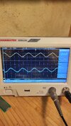
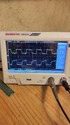
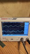
Notes : I decided to combine a simple "led blinker" circuit changing the values to aim at a 1.5kHz oscillation frequency. I then added 3 RC filtration stages in series to turn the "square" output of the oscillator into triangle and sine. Note : The RC filters should match the oscillator frequency to effectively integrate the signal.
Pros/Cons : High output impedance, but this also protects the circuit from what could backfire from the output wire. So quite useful for a test circuit indeeed.
Many waveforms in one.
Good tension swing for testing (10Vp-p on a 12V input for the square wave, 2Vp-p on the triangle, 1V p-p on the sine after 3 filters), can be lowered with a tension bridge.
Upgrades : a supply tension regulator (zener diode based would be easy to implement and suitable since power is low).
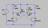
2) Class A amp
Why : To practice amplification of faint signals.
Schematic : (attached).
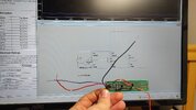
Notes : It is a 2-staged amplifier. First stage is a common collector with gain 10, which amplifies incoming AC tension by a factor 10 but shows poor impedance. 2nd stage is an emitter follower (common emitter) to have a more decent output impedance (measured at 18 Ohm : 6V output no load and 5.54V output with a 220 Ohm load.).
Both transistors used are BC337 NPNs.
Pros/Cons : Simple to build BUT output impedance is too high to drive 4 Ohm speakers. Also, the BC337s burn in a second when trying to output 1V peak-peak to a 4 Ohm speaker.
Upgrades : Use beefier second stage transistor, like BC120 + heatsink. Find a way to lower output impedance.
Hope you "like it" and hope it may be useful to someone someday !
I strongly recommend lectures #198, #273 and #356 of Youtuber w2aew which greatly taught and inspired me !
My 1st post here was a few weeks back and I failed at creating a class A amplifier at the time. With the help of members and a lot of online browsing, I managed to edit and manufacture 2 small circuits I'm proud of and want to share here for the next beginners to be found.
1) OSCILLATOR
Why : I needed a signal source that would be reliable and would not need me to hook my precious phone to a circuit that could fry it (I fried my sound card. Twice. Never again.)
Schematic : (attached, random R and C values, mine land on 1.6 kHz. Must be adapted to the target frequency. ).
Notes : I decided to combine a simple "led blinker" circuit changing the values to aim at a 1.5kHz oscillation frequency. I then added 3 RC filtration stages in series to turn the "square" output of the oscillator into triangle and sine. Note : The RC filters should match the oscillator frequency to effectively integrate the signal.
Pros/Cons : High output impedance, but this also protects the circuit from what could backfire from the output wire. So quite useful for a test circuit indeeed.
Many waveforms in one.
Good tension swing for testing (10Vp-p on a 12V input for the square wave, 2Vp-p on the triangle, 1V p-p on the sine after 3 filters), can be lowered with a tension bridge.
Upgrades : a supply tension regulator (zener diode based would be easy to implement and suitable since power is low).
2) Class A amp
Why : To practice amplification of faint signals.
Schematic : (attached).
Notes : It is a 2-staged amplifier. First stage is a common collector with gain 10, which amplifies incoming AC tension by a factor 10 but shows poor impedance. 2nd stage is an emitter follower (common emitter) to have a more decent output impedance (measured at 18 Ohm : 6V output no load and 5.54V output with a 220 Ohm load.).
Both transistors used are BC337 NPNs.
Pros/Cons : Simple to build BUT output impedance is too high to drive 4 Ohm speakers. Also, the BC337s burn in a second when trying to output 1V peak-peak to a 4 Ohm speaker.
Upgrades : Use beefier second stage transistor, like BC120 + heatsink. Find a way to lower output impedance.
Hope you "like it" and hope it may be useful to someone someday !
I strongly recommend lectures #198, #273 and #356 of Youtuber w2aew which greatly taught and inspired me !