Continue to Site

Welcome to our site!

Electro Tech is an online community (with over 170,000 members) who enjoy talking about and building electronic circuits, projects and gadgets. To participate you need to register. Registration is free. Click here to register now.

  • Welcome to our site! Electro Tech is an online community (with over 170,000 members) who enjoy talking about and building electronic circuits, projects and gadgets. To participate you need to register. Registration is free. Click here to register now.

My first schematic of a 2-channel relay board

StealthRT

Member
Hey all this would be my first try at creating a schematic in KiCad.

The schematic is a basic 2-channel relay.

The inputs are automotive 12v and gnd. This gets converted to 5v by the K78L05-1000R3.

The Wemos D1 mini has 2 digital pin outs that are 3.3v going to the LTV-356T with a 200 kOhms resistor in between.

From there it goes to a 1k resistor and then to the PMBT3904. Between that and the G5LE-1 relay is a 1N4007F.

In that same area is another 200 kOhms resistor that’s connected to an LED.

The outputs and inputs are the 2pos and 4pos 3.5mm Pitch Terminal Block Connector 300V 8A.

Just want to make sure my values are good and the components I have selected are suitable for my application. Please let me know if I am missing anything or have a value incorrect. Thanks!

image

Question also asked on:
maker.pro, electronics-lab, allaboutcircuits, kicad, Elec. Stackexchange
 
The only direct experience I have where slow release could have been a factor was on the control board of a frost-free refrigerator. For some reason the relays were DC and were powered from 230 V 50 Hz mains using a current limiting capacitor and a full bridge rectifier. On one of the relays the NO contacts were welded shut.

Now I don't know whether the slow reduction in the current on that fridge had anything to do with the failure. The fridge would have been built down to a price and the compressor and defrost heater would have been cycled on and off several times a day at least, so the relays would probably been stressed quite hard anyhow.
 
View attachment 142927
The peak voltage on the transistor will be increased by a factor of R100/[relay resistance] so you must make sure that the peak voltage is still less than the transistor maximum Vce.

The resistance of the G5LE relay is 39 Ohms. The current at 5 V is 128 mA. When the transistor turns off, that current will flow through R100. If R100 is 220 Ohms, that will give a voltage of 28.2 V across R100. The voltage between the collector and emitter of the transistor is that 28.2 V plus the supply voltage plus the diode voltage, so about 34 V. That is OK for a transistor rated at 40 V or more.

The resistance in the freewheel circuit is 39 + 220 Ohms, which is 6 - 7 times larger than it would be if the diode were directly in parallel with the relay coil, so the current in the coil will reduce about 6 - 7 times faster.

The LED current is limited by both R100 and R101. If the LED voltage is 2 V, R101 is 0 Ohms and R100 is 220 Ohms, the LED current is 13 mA. R101 can be increased to reduce the LED current if required.

The connection with R100 and the LED in parallel with the diode instead of in parallel with the relay coil prevents the reverse voltage spike of 28.2 V being applied to the LED.

In your application it may not matter if you turn off the relay coil slowly. It will still appear instant to someone watching. The curves in the data sheet show that the life of the relay is reduced quite a lot as the load current goes up, and inductive load reduce the life.

Many automotive relays have a resistor built in, in parallel with the coil, and no diode. The transistors that drive the relays have to be rated to 100 V or so, if there is no external diode, but they probably would be anyhow. Having no diode means that the coil polarity doesn't matter.

Thank for for all that knowledge, Diver300!
 
Final schematic:
1) Removed LTV-356T Opto.
2) Added 10k between Base and Emitter of the PMBT3904.
3) Connected LED to 5v line instead of the collector line on the PMBT3904.
4) Replaced 200R with 220R.
5) Replaced normal fuses for blade fuse holders.
6) Replaced 18v G5LE-1 relay with the correct 5v relay G5LE-1A4 DC5 model.
7) Added a solder pad for the always on (AO) +12v line.

1696195223533.png
 
My first thought was that the rule could relate to diode polarity vs. terminal polarity?
Automotive relays identify terminal 86 as the positive terminal coil, and 85 as ground. The numbers are marked on the housing, the + and – may or may not be. But of course, polarity on the coil doesn't matter....unless a back-emf diode is installed. I've heard of people having a relay that doesn't work "for know apparent reason" or a replacement relay that doesn't work because there's an unexpected diode installed. The relays with diodes don't have any particular ID, so it's difficult to know.

Other relays may have diodes too. There recently was an article from EDN about a large-scale commercial product that failed until the relays "were primed" on the test stand. Nobody took time to figure out why until a revised version of the relays were used, and these failed even if "primed". Finally they investigated the problem. The relays included an internal diode and had been wired with the wrong polarity. "Priming" them on the test stand provided enough current to blow the diode.

The upgraded relays had higher current diodes – the test stand couldn't provide enough current for "priming".
 

Attachments

  • SmartSelect_20231001_152038_Edge.jpg
    SmartSelect_20231001_152038_Edge.jpg
    51.7 KB · Views: 88
Another way is not to use a standard freewheel diode arrangement. Instead, connect a zener diode across the driver transistor, between the coil driving point and GND. The main advantage is that the "flyback current" of the coil is dumped into GND rather than into Vcc.

The zener voltage must be at least equal to Vcc so it is not conducting all of the time, but it can be greater. For example, if you have a 12 V system and use an 18 V zener, the relay will de-energize much more quickly than with a standard diode, and most of the coil energy will go through the zener to GND.

Potter and Brumfield has an app note about this. Also, TI has a line of power driver ICs that has this type of protection built-in.

ak

The P & B ap note :


Interesting....


Regards, Dana.
 
I had noticed before that when the relay is being turned off, the coil current can go back up very briefly as the armature moves. Figure 2 on the P & B app note shows that.

What I hadn't realised is that the armature can actually slow down and even reverse direction. I had thought that the armature would just move more slowly when I diode was used than when the suppression uses a larger voltage.

Also, when there is no suppression, figure 1 shows there is a voltage on the relay coil for a few milliseconds after the current is turned off. I hadn't realised that before, but it makes sense as the moving armature is actually generating a voltage.

The last paragraph in the P & B app note is basically saying that the contact life has to be worked out by the user, and the ratings can't be trusted where any suppression is used. As almost all relays have some suppression, the contact ratings aren't much use.
 
Last edited:
The last paragraph in the P & B app note is basically saying that the contact life has to be worked out by the user, and the ratings can't be trusted where any suppression is used. As almost all relays have some suppression, the contact ratings aren't much use.

Very interesting! I'd like to see the relay movement in slow motion, with & without diodes!

Also very different to the Omron G2R relays we use in machine control systems??

All the DC types can have a status LED, diode, both or nothing depending on the exact part number. The contact ratings & life tables make no distinction between these variants.

The only notes re. the diode versions are a slightly longer release time and warnings about reverse voltage damaging the diode.


The Schneider docs for the power contactors we use likewise have fixed contact ratings & life, regardless of the coil suppression - they have optional clip-in diodes for DC ones. (Though some of the larger types include an SMPSU within the coil module).
 
Hi

We used literally hundreds of relays on traffic control systems in my former life. We always used suppression diodes across the coils unless the was a good reason not to. Those systems were extremely reliable, working for decades. I wouldn’t be surprised if some were still in service today.

Anyway, I’ve seen diode supressors cause slow (1-2 sec) drop out, but only in large relays with physically large cores/coils.
 
Hi

We used literally hundreds of relays on traffic control systems in my former life. We always used suppression diodes across the coils unless the was a good reason not to. Those systems were extremely reliable, working for decades. I wouldn’t be surprised if some were still in service today.
I'd be surprised if they weren't still working, relays are very well tried and tested technology, and generally extremely reliable.

Unfortunately there are a tiny number of members on here who's purpose in life appears to be to pop in any post they can and preach 'doom and gloom', by comparing the post to an extremely unlikely occurrence, and completely ignoring the sensible answer to a simple question.
 
Here's the sim of a 100Ω, 1.5H inductor (emulating the relay coil) with just a Si diode suppressor.
As you can see, the current rise and fall times are quite similar, so I see no need to add a resistor or use a Zener, unless you need the relay release time to be faster than the operate time.

I suspect, that even if you deliberately slowed down the release voltage, the relay contacts would still move about the same speed once the magnetic field goes low enough that the armature releases from the coil face, which is mainly determined by the contact inertial and spring tension.
Consider that the release voltage (current) of a relay is well below its operate voltage, so the remaining magnetic field that would slow down the contact release is relatively small.

1696776542991.png
 
You should never design anything without specs. Otherwise, you will make a lot of assumption errors and have no tests planned to verify the design is ok.

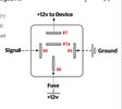
The simple relay operation is not so simple when reactive loads are used. This release time on inductive loads is what creates the flyback arc voltage on the contacts that will burn the silver alloy much faster than a resistive load. A lower MAY SWITCH spec. for coil current will extend this time and a lower diode resistance will extend this time due to the low resistance in a saturated coil snubber diode. The inductive load must also have a snubber on the contacts to protect it but now at much higher power levels than the relay coil snubber.

Low current snubbers may be resistive to protect the Vceo of the NPN transistor where Icoil * R =< 90% Vceo but if the relays have a very low MAY SWITCH OFF Threshold << 30% then a Zener and diode in series is best with a transistor that is much higher Vceo rating than the common 40V PN2222A.

Note that this 10A relay fails rapidly after a 7ms inductive load great than 4 A.

1696771061895.png
1696788299209.png

1696772249070.png


Those who do not understand why some Relays fail faster than others may appreciate Omron's excellence for reliability but not be aware of the assumptions. Omron once had over 15 yrs ago far more technical data and also invented moving coil technology but has since retracted most of this in favour of promoting solid-state relays.
- from archive.org

1696775301805.png


- The turn-off time is mechanically 5ms, but electrically Tau is controlled by snubbing resistance, Rs
- Resistive snubber voltage must be less than Q1 Vceo breakdown voltage V= Icoil*Rs.
- This has serious implications considering the flyback contact voltage will ionize in microseconds and quickly reach arc temperatures as the silver alloy contact surface heats up and degrades.

Let's examine the specs.:
- mechanical life 10 million cycles
- electrical life 0.1 million cycles resistive only 0.1A 5Vdc 2-sec cycle (minimal contact temp. rise)
- If you extrapolate the above test for Ir = 7A DC , I expect MTBF to reduce with resistive non-arc switches to MTBF/10

What happens with inductive loads on power contacts not protected from arcing?

TE article describes how the hot contacts from inductive arcs become stuck, and welded together.
Relay users often desire to know the inductance of the relay coil they are using so they can determine the energy released by the coil upon de-energization.

Coil inductance with the armature seated is greater than that when unseated. This is because inductance varies directly with incremental permeability ( µ ) and inversely with the length ( l ) of the magnetic circuit path. The air gap in the magnetic circuit of an unseated armature both decreases µ and increases l. Of course, the greater the inductance, the greater the energy released into the coil circuit upon de-energization.

Inductance also will vary with coil voltage, since permeability varies with magnetizing force which, in turn, is determined by coil voltage. For values most meaningful to the circuit designer, inductance should be measured under conditions that simulate actual relay service; that is, at rated voltage and current.

Inductance with the armature seated represents actual application conditions at the instant coil power is removed. When coil power is removed, the coil generates a counter voltage, -e = L(di/dt), which is fed back into the switch circuit. Depending on energy levels, this voltage surge may adversely affect the life or operational characteristics of the switch that controls the relay coil. ( For methods to protect the switch, see "Coil Suppression Can Reduce Relay Life", 13C3264.)

The inductance of DC coils should be measured by the L = tR method by use of an oscilloscope. This method requires the application of rated DC voltage to the coil while physically holding the armature seated. The value, t, is the time for coil current to increase to .623 of its steady state value, and R is the coil DC resistance in ohms as measured by an ohmmeter.

The inductance of AC coils may be determined by measuring coil voltage and current and actual power consumed by the use of a wattmeter. The product of coil voltage and current is the "VA" in the following equation, "W" is the power as given by the wattmeter. R = measured DC resistance in ohms.


If a wattmeter isn't available, inductance may be determined by use of a dual-trace oscilloscope, one input of which is fed by a current probe. In this method, rated voltage at the proper frequency is impressed on the coil, and the time displacement, t, of applied voltage and coil current is measured by the oscilloscope. Inductance is calculated as above, where:

Formula 2.

t = time in ms by which coil current lags coil voltage

But when properly and conservatively designed, Relays ought to last 10k to 100 k cycles depending on the quality of the design and the components.
 
Last edited:
I decided to do a quick practical measurement of the speed of an automotive relay, with and without a diode.

TLDR:- The time between the NO contact opening and the NC contact closing is about 2.5 times as long with a diode in place.

Here is the circuit that I used:-

relay circuit.PNG

The Omron E2K is a capacitive proximity sensor that I used as a device that would switch quickly, and I had one available. The two 3.3 kOhm resistors allowed the oscilloscope to see the different voltages for the NO and NC contacts, because there is quite a lot of switch bounce going on.

The relay was a standard automotive relay, Land Rover part no. DH22-14B192-DA. The 680 Ohm resistor is contained within the relay.

With the diode, this is what happened:-
with_diode.PNG


The NO contact opened after 10 ms and it took 2.7 ms from that contact opening until the NC contact closed.

I've not shown the circuit without the diode, but the only change was removing the diode. This is what happened:-

without_diode.PNG


The NO contact opened after 2.6 ms and it took 0.93 ms from that contact opening until the NC contact closed.
The NC contact bounces for 5 ms when the diode is removed, compared to 2.5 ms when the diode is there.

The voltage waveform with the diode missing show the big hump as the armature separates. Modelling a relay coil as a simple inductor clearly has limitations.

I think that this shows that the speed of the NC relay contacts opening will be quite a bit quicker when the diode isn't fitted.
 
I think that this shows that the speed of the NC relay contacts opening will be quite a bit quicker when the diode isn't fitted.
True.
But that typically is not an issue in most relay applications.
 
Hey all this would be my first try at creating a schematic in KiCad.

The schematic is a basic 2-channel relay.

The inputs are automotive 12v and gnd. This gets converted to 5v by the K78L05-1000R3.

The Wemos D1 mini has 2 digital pin outs that are 3.3v going to the LTV-356T with a 200 kOhms resistor in between.

From there it goes to a 1k resistor and then to the PMBT3904. Between that and the G5LE-1 relay is a 1N4007F.

In that same area is another 200 kOhms resistor that’s connected to an LED.

The outputs and inputs are the 2pos and 4pos 3.5mm Pitch Terminal Block Connector 300V 8A.

Just want to make sure my values are good and the components I have selected are suitable for my application. Please let me know if I am missing anything or have a value incorrect. Thanks!

image

Question also asked on:
maker.pro, electronics-lab, allaboutcircuits, kicad, Elec. Stackexchange

No problem with the diode suppressors, but the leds are not wired correctly.
 

Latest threads

New Articles From Microcontroller Tips

Back
Top