An amplifier with a high open-loop voltage gain can use a lot of negative feedback to reduce the gain to a useable amount, reduce the distortion to be extremely low and increase the bandwidth. Haven't you heard about opamps? An OPA134 opamp has an open loop voltage gain of typically one billion. With its gain reduced to 10 with lots of negative feedback then its low frequency distortion is only 0.0008%.
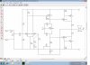
Your compounded output transistors are called Sziklai pairs. They have no voltage gain but instead have a high current gain.
Their high current gain allows the driver transistor to have a low current so that it doesn't overheat and so that it can have a high value collector load resistance so it can have a higher voltage gain.