Continue to Site

Welcome to our site!

Electro Tech is an online community (with over 170,000 members) who enjoy talking about and building electronic circuits, projects and gadgets. To participate you need to register. Registration is free. Click here to register now.

  • Welcome to our site! Electro Tech is an online community (with over 170,000 members) who enjoy talking about and building electronic circuits, projects and gadgets. To participate you need to register. Registration is free. Click here to register now.

Rookie needs help to understand why his A-class amplifier doesnt work (measurements and schematic attached)

GreenGecko7

New Member
Dear all, nice to meet you !

I recently invested in some tools to build amplifiers (my first oscilloscope + all-rounder C and R kits.). My end goal is to build an AM radio.
I have some basic knowledge in electronics : I have studied transistors and OP Amp functioning during my college masters degree. I also have a few Arduino projects under my belt.

However my 2 last tries at building a functiuning Class A amplifier failed. I need some help to understand why !
I based the diagram on this famous video :
And I adapted the values to fit my 12.2V switch-mode power supply.

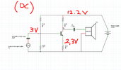
Attached the schematic, in red are the DC measurements made via oscilloscope/multimeter.
Also, no AC component survives the first capacitor : the oscilloscope probing remains flat at +3V DC (DC coupling) when probed on the transistor base with reference on the ground.

Can you help me understand what fails, and suggest me fixes?
I can probe additionnal points if you tell me what to look for specifically.

Thanks a lot in advance ! :)

Benjamin, from France
 

Attachments

  • Circuit class A as made with measurements.PNG
    Circuit class A as made with measurements.PNG
    104.8 KB · Views: 93
I will aim at free bands dedicated to "amateurs" as shown in the following document :

You still must have an appropriate Amateur Radio (Ham) licence to transmit on any band!


Re. the audio amp -

The TIP120 & 125 are Darlington transistors, so have a base-emitter drop of around 1.2V
You will lose a lot of input signal before either starts to conduct.

It would need four diodes in the base bias chain to approximate the same voltage as between the bases.
Without adjustment, it's still possible to have insufficient or too much bias though.

You still have no voltage gain though, so only the same signal level as the source.
 
That 1W is GREATLY more than the few milliwatts of your single transistor effort. Power output (with a correctly designed circuit) is dependent on power supply voltage, and speaker impedance. Using an output transformer, simply alters the effectvie impedance of the speaker.


I'm rather bemused it's called a 'Japanese radio', it's just a bog standard radio design back from the days of germanium PNP transistors (NPN either weren't available yet, or were even more horrendously expensive) - probably originating from a Mullard data sheet?. Once NPN germanium became reasonably priced, the transformers were mostly dumped, and quasi-complementary output stages introduced instead?.

I suppose it could be 'Japanese', as they started producing versions of the older designs, after European manufacturers had moved on to more modern transformer-less ones.
The original design may have been Swiss, Dutch, German or American using the 2N1524: RCA Transistor Ge PNP.

I don't know who was first or better but I first observed that the Japanese excelled at the mass production of miniature radios in the early '60's with precision tuneable ferrites and vertical axial parts folded to save space like a radial part.

If @Geckos has the desire to get into Ham Radio, there are clubs all around the world. It is best to understand that RF will take some time to understand the theory and practical limitations of impedance ratios, resonance, double-tuned filter coils, IF function, LO function, image rejection. Start search for Theory of Operation and keep reading the basics until you can understand.

Here are some links to get started. Making an Audio Pre-Amp and Power Amp work perfectly is your 1st challenge. The radio stuff is much easier to buy than make. Join a Ham club for fun.


https://www.virhistory.com/ham/rrab/manuals.htm (many old links are gone but might be found using archive.org


Bob Pease had some jewels on wisdom on analog stuff.
Scan for schematics you recognize and read about them.


Falstad simulator of a 741 Op Amp internals with a gain of 1000
 
The handiest tool I found for checking and modifying an amp, or a circuit, network, component, etc, is a function generator. It lets you sweep a number of parameters and watch the effects on the scope. It eliminates the guess work and tells you immediately if you really understand the circuit as well as you think you did.

One can change the value of a component while sweeping and watch the effect.
 
If you want the simplest power amp. it will look like this 2W for $1.31 IC with unity gain using 5V.
1698123500682.png
 
Dear all,

Thanks a lot for the provided resource ! I'll kepp the schemes and web adresses in a bookmarked file.
Damn I wasn't aware I needed to join a club to emit : I genuinely thought some frequencies were "free" and you just had to either listen or sweep and find an un-used spot in the frequencies..!

As you mentionned, I'll try to build my own preamp and power amp in the first place, then we'll see.
 
Hello all,

Quick update, I built an OP-amp piloted class B amplifier, and it works just fine !

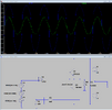
Attached the schematics, LTSpice simulation and actual measurements.

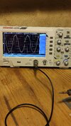
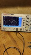
It relies heavily on the slew rate of the OP Amp. Yet, for music, the quality is decent enough as cross distorsion is not very intense. As you can see, output signal is quite clean indeed, more than on the simulation !

The OP Amp could only deliver 25 mA of current, that is to say 0.1V on a 4 Ohm load. The transistor stage pumps output current all the way up to 750 mA !

Limitation : the plastic-cased 2n2222 and 2n2907 heat up at full power. I believe adding a 2nd stage with heatsinked transistors and the same bootstrap would be a fine addition to increase reliability and power output.
 

Attachments

  • classe B pilote par OPAMP.PNG
    classe B pilote par OPAMP.PNG
    61.4 KB · Views: 69
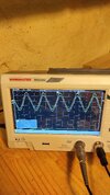
  • amplified signal with low impedance.jpg
    amplified signal with low impedance.jpg
    619 KB · Views: 70
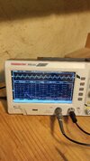
  • Original signal.jpg
    Original signal.jpg
    1.5 MB · Views: 72
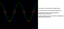
  • visible jump of OPAMP output around signal crossover.jpg
    visible jump of OPAMP output around signal crossover.jpg
    1.6 MB · Views: 72
Use your FFT capability to look at harmonic distortion as another measure of
its ability to ampo w/o distortion.


Regards, Dana.
 
One expects 750 mA * (12 V+750mA*4ohm) to make a 100 mW transistor rather warm.

Try TIP105 is TIP100 with mica insulators on a CPU heatsink. Then expect 20W audio on 4 ohms.
 
Even though the gain is only 2 times, the distortion is horrible.
The small output transistors are seriously overloaded when the volume is up just a little.

You need to make a class-AB amplifier that has real Power Transistors at the output.
 
Hi all,

Here are the FFTs of my input and output signals, as well as the 2 side to side. Quite similar to me ! Also, the signal isn't a pure sine : it is generated by a homemade oscillator + integrator circuit. It is slightly crooked but it allows me to have a reliable AC signal without having to connect my phone to the breadboard.

Note : I sadly don't have the Lissajous display on my cheap, Chinese oscilloscope ! It would have been nice to witness distorsion.

Anyway to me, side to side, these 2 signals look similar ! They also sound clean.
Even though the gain is only 2 times, the distortion is horrible.
The small output transistors are seriously overloaded when the volume is up just a little.

You need to make a class-AB amplifier that has real Power Transistors at the output.
audioguru, are you sure you comapred input and output? I agree, distorsion on the "opamp-output" probing is disgusting but it allows to drive the transistors, effectively overcoming crossover distorsion by jumping from -0.7V to +0.7V. This intermediate, high impedance signal isnt connected to the speakers.

Though I agree, I'll work on a biased AB in the upcoming days. Much cleaner and versatile, and viable at higher frequencies.

I'll base my schemes off the videos #198, #273 and #356 of this *wonderful* channel ;) :
 

Attachments

  • input and output side to side.jpg
    input and output side to side.jpg
    1.3 MB · Views: 66
  • FFT output signal.jpg
    FFT output signal.jpg
    1.2 MB · Views: 70
  • FFT original signal.jpg
    FFT original signal.jpg
    1.1 MB · Views: 70
Even though the gain is only 2 times, the distortion is horrible.
The small output transistors are seriously overloaded when the volume is up just a little.

You need to make a class-AB amplifier that has real Power Transistors at the output.
Don't forget that the crossover voltage error is reduced by the feedback gain vs f, so with high GBW OA's (not a 741) it is crude but can work. But the design may improve to use the inverting input rather than 1+ Av. https://tinyurl.com/yo8lu4rf
 
Last edited:
Audio amplifiers built lately should not produce all the distortion in yours.
 

Attachments

  • Class-B amplifier distortion.png
    Class-B amplifier distortion.png
    30.1 KB · Views: 68
Audio amplifiers built lately should not produce all the distortion in yours.
Since the amplitude error is slew rate limited (and thus not show up at low f inputs) , what spurious frequency would you expect this distortion in a high slew rate OA? (even though we know it is easy to avoid this error.)
 
Hi,

The simulated circuit above uses a "generic" OpAmP for modeling purposes only. TL072CP werent available on LTSpice.

I believe the generic OpAmp has quite a bad slew rate compared to the one I used on the breadbord; hence I get better results on the scope than on the simulation.

Since the slew rate of TL072CP is 13 V/µs, we can expect to have decent results all the way up to f = 100 kHz in order to leave 100 times the 0.1µs required by the OPAmp for the 1.4V crossover jump to keep the distorsion under 1%.

f = 1/T = 1/(100*0.1*10^(-6)) = 10^5 Hz

I agree 1% is a lot, now for audio purposes slew rate induced distorsion would only be 0,1% at 10 kHz.

To conclude, this is a dirty way around and it can not be applied to high-frequency signals like the 3 MHz I am aiming at :)
 

Latest threads

New Articles From Microcontroller Tips

Back
Top