johnyradio
Member
Hi
Ideally, i'm looking for a simple frequency divider that i can feed a square wave, using only schmitt inverters or schmitt NAND (just one if possible). Should work over a wide input-frequency range.
The posts below provide a schematic for a so-called "flip-flop" (which i think is really a toggle, not a flip-flop) using two schmitt inverters.
https://www.electro-tech-online.com/threads/electronic-switch.26093/#post-181844
http://forums.adafruit.com/viewtopic.php?f=8&t=36970&p=607457#p607457
http://www.learningaboutelectronics.com/Articles/Touch-on-off-circuit-with-a-7414-inverter.php
The circuit is based on a switch, not a clock, so would not work as-is for my need. But, maybe someone can see a way to make this work as a divider with a clock-input instead of a switch? Or, some alternate flip-flop circuit using schmitts?
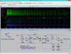
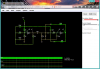
I wired up the above circuit in falstad
http://tinyurl.com/ya8cz2nm
Issues:
Any ideas for a true flip-flop divider based on Schmitts?
thx
Ideally, i'm looking for a simple frequency divider that i can feed a square wave, using only schmitt inverters or schmitt NAND (just one if possible). Should work over a wide input-frequency range.
The posts below provide a schematic for a so-called "flip-flop" (which i think is really a toggle, not a flip-flop) using two schmitt inverters.
https://www.electro-tech-online.com/threads/electronic-switch.26093/#post-181844
http://forums.adafruit.com/viewtopic.php?f=8&t=36970&p=607457#p607457
http://www.learningaboutelectronics.com/Articles/Touch-on-off-circuit-with-a-7414-inverter.php
The circuit is based on a switch, not a clock, so would not work as-is for my need. But, maybe someone can see a way to make this work as a divider with a clock-input instead of a switch? Or, some alternate flip-flop circuit using schmitts?
I wired up the above circuit in falstad
http://tinyurl.com/ya8cz2nm
Issues:
- Seems highly sensitive to input on-time.
- Getting strange oscillations.
Any ideas for a true flip-flop divider based on Schmitts?
thx