Continue to Site

Welcome to our site!

Electro Tech is an online community (with over 170,000 members) who enjoy talking about and building electronic circuits, projects and gadgets. To participate you need to register. Registration is free. Click here to register now.

  • Welcome to our site! Electro Tech is an online community (with over 170,000 members) who enjoy talking about and building electronic circuits, projects and gadgets. To participate you need to register. Registration is free. Click here to register now.
Status
Not open for further replies.

mading2018

Member
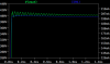
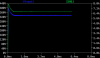
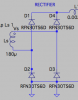
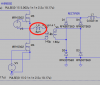
I think the output current I get from the DC/DC converter is way too low, it should be at least 6-8 A, not in mA that I got. I think the resistor that I have in the end of the converter is needed in order to obtain 400 V.
Do anyone have any suggestion what could be the problem?

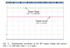
I found a similar converter in a research paper, where they obtained 400 V output voltage (Vo) ( which I got I think) and current output (Io) to 8 A.
See the attached files please and thank you.
 

Attachments

  • forum.png
    forum.png
    52.7 KB · Views: 227
  • forum1.png
    forum1.png
    86.9 KB · Views: 242
  • OBC_DCDC.asc
    5.2 KB · Views: 197
  • fourm2.png
    fourm2.png
    47.9 KB · Views: 226
That would imply a load resistor R1 of 400/6=6.7 ohms.
Also: 400 volts at 6 amps is 2400 watts. Do you have your transformer sourced yet?
 
Ohm's Law says that the current in the 2k resistor at the output is 400V/2000 ohms= 200mA.
If you want 8A then try 400V/8A= 50 ohms but it will heat with 400V x 8A= 3200W!
 
Ohm's Law says that the current in the 2k resistor at the output is 400V/2000 ohms= 200mA.
If you want 8A then try 400V/8A= 50 ohms but it will heat with 400V x 8A= 3200W!

Oh, yes, thats true. I totally forget the basic law. It looks better now, maybe I do not obtain up to 400 V, a lower than that, and a current for around 7 A.
Yes, I know that power output is high, but its a charger for a vehicle I trying to simulate, so it should be high.
 

Attachments

  • forum0.png
    forum0.png
    39 KB · Views: 208
Do you guys have some idea how I can mitigate the ripple more for the output (both current and voltage)? I asking cause, it is for charging applications for a plug-in-hybrid-vehicle's battery .
 
I asking cause, it is for charging applications for a plug-in-hybrid-vehicle's battery .

Batteries are not very fussy about ripple so needing high ripple filtering and control is rather pointless in this application.

Also in a properly designed and built EV teh HVDC power systems are isolated from the vehicles body so needing additional stages of isolation between the primary AC line power source and the vehicle are not as critical as you may be thinking they need to be.

One reference to it here.

https://books.google.com/books?id=fhNLk4afdz0C&pg=PA149&lpg=PA149&dq=are+ev+batteries+isolated+from+the+frame+of+the+vehicle&source=bl&ots=kKTEJHM1KJ&sig=UIdtieEukQdC194YH4g12JBoHcA&hl=en&sa=X&ved=0ahUKEwjNwfqnuIDaAhVOS6wKHe04Dl4Q6AEIQDAC#v=onepage&q=are ev batteries isolated from the frame of the vehicle&f=false

Given that design fact a fair amount of EV charging systems do not use full isolation from their AC side to DC side but rather use simple but high powered buck/boost type converters only.

One of many reference articles on the various charger topologies here. Depending on the application some do and some don't.

https://pdfs.semanticscholar.org/b6b8/7f4a11ece51c932e36ea45b19fe3497b4929.pdf

Application specific non isolated charger for 250 -450 VDC battery systems using universal 85 - 275 VAC input.
https://publications.lib.chalmers.se/records/fulltext/162602.pdf

No need to over complicate things if the rules don't specify that you need to. ;)
 
Last edited:
Your rectifier diodes have a 45V breakdown rating :(.
 
You mean I need to have a higher breakdown rating? Like around 400 V?

In most power supplies you want to have around a 2:1 or better voltage rating on all of your components and preferably a 3:1 or better for current on primary power circuit diodes and switching devices.

You can get by with les if you really know what you are doing and have very tight control over the working limits of the system but for general DIY construction where it's unlikely you have every detail worked out through real live hands on circuit test and refinement more is better. Theoretical ideal based simulations are a poor stand in for hard live reality based testing and refinement procedure.

Ah, I see. So I picked another component for the diode, I guess this one should be okay to use, right?
 

Attachments

  • forum.png
    forum.png
    23.4 KB · Views: 208
  • forum2.png
    forum2.png
    30.5 KB · Views: 214
Oh, by the way, do you think I need to add an another inductor on the primary side called "L_4"? I have seen in quite many schematics, that they are frequently used. But is it necessary to add that? What's the the purpose to have an another inductor there?
 

Attachments

  • OBC_DCDC.asc
    5.1 KB · Views: 188
  • L4.png
    L4.png
    51.3 KB · Views: 216
Last edited:
I tried to select a sufficient transistor, but it seems not to work. I selected 200 kHz as switching frequency.
I know it works for lower switching frequency (100 kHz), but I am suppose to select 200 kHz. (This is because the size of components should be smaller).

Could someone please check the circuit? :) have a great weekend as well
 

Attachments

  • OBC_DCDC (1).asc
    4.1 KB · Views: 196
Last edited:
The timing of the switching of the FETs is wrong. You have shoot-through because the top and bottom FETs of the left-hand side of the bridge are on simultaneosly. Likewise the right-hand side of the bridge.
 
Status
Not open for further replies.

Latest threads

New Articles From Microcontroller Tips

Back
Top