Continue to Site

Welcome to our site!

Electro Tech is an online community (with over 170,000 members) who enjoy talking about and building electronic circuits, projects and gadgets. To participate you need to register. Registration is free. Click here to register now.

  • Welcome to our site! Electro Tech is an online community (with over 170,000 members) who enjoy talking about and building electronic circuits, projects and gadgets. To participate you need to register. Registration is free. Click here to register now.

atari punk color organ

MrDEB

Well-Known Member
curious if this has ever been done or even possible.
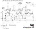
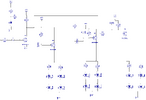
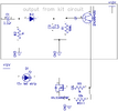
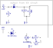
Am playing around building an Atari Punk Console but thinking of adding LEDs that are controlled by 3 band pass filters (low, mid high)
this is for another project for grandson to drive his parents nut with the sound and amuse him with the LEDs.
 

Attachments

  • vibra punk circuit.png
    vibra punk circuit.png
    85.9 KB · Views: 133
  • color organ schematic.pdf
    106.7 KB · Views: 140
REVISING THE COLOR ORGAN. Using A SIMPLIFIED CIRCUIT THAT DOES NOT USE THE OP AMPS.
Original design used 2n3904 transistors, but using a MOSFET instead will conserve battery power a little
attached both designs
 

Attachments

  • easy-led-color-organ_circuitesize.jpg
    easy-led-color-organ_circuitesize.jpg
    72.9 KB · Views: 119
  • SIMPLE ORGAN.png
    SIMPLE ORGAN.png
    56.6 KB · Views: 112
I don't see why you imagine the FET version would conserve any battery power?, at a quick glance it doesn't look like it would even work, with the FET's looking to be permanently biased ON?.

Both are utterly crap circuits anyway, and performance would be poor.
 
here is a video of the circuit with 2n3904 transistors.
My understanding and simulation using easyeda the PNP transistor loses about 1.5 volts aprox. The MOSFET way less.
 
Original design used 2n3904 transistors, but using a MOSFET instead
Be careful. The original design uses a 2N3904 + 2N3906 transistors (the schematic shows the wrong symbol for the first transistor).

You can't just replace the 2N390x with a fet. Build the circuit as originally shown if that's what you want.
 
here is a video of the circuit with 2n3904 transistors.
My understanding and simulation using easyeda the PNP transistor loses about 1.5 volts aprox. The MOSFET way less.

Your understanding appears to be misplaced - 'if' the transistors are turned fully ON, then they will only lose a couple of hundred millivolts, but this poor circuit is unlikely to achieve that. I don't see how the FET circuit will improve on that?, it depends on how well they are driven - but the circuit you posted appears to have them permanently biased ON anyway?.

In any case it doesn't matter if you lose a little voltage across the transistors or FET's as LED's are current driven - you've already got series resistors to lose voltage and lower the current, the drop in the transistors/FET's is only going to add a little to that.

As others have said, you can't just repace transistors with FET's, and there seems no advantage anyway.
 
Well we're back on random circuit changes that will entirely stop it working :D

As you were told the FIRST transistor was drawn with the wrong polarlty, why did you leave that one wrong and change the other three?.
 
well I assembled the Jamco color organ kit but want to use MOSFETs to control up to 5 amps per channel (3 channels) but not real sure. plan to use IRF 520 N CHANNEL MOSFETS.
have attached the schematic for the assembled color organ kit
 

Attachments

  • color organ schematic.pdf
    106.7 KB · Views: 121
That will not work as you hope, it's unlikely anything would ever give any output.

You need to use P-channel MOSFETs (or PNP transistors) driven from the collectors of the 2N3904s in the original circuit.

In other words, the higher power output stage replaces the LEDs in the original.
 
Perhaps just eliminate the transistor and just use the N channel MOSFET?
Going to connect a 555 timer on a breadboard and experiment using the MOSFET.
 

Attachments

  • mosfet conversion2.png
    mosfet conversion2.png
    33.9 KB · Views: 96
here is something I found but why the led and 1K resistors?
 
Indication that it's on, and to ensure the FET switches off properly.

See post #12. You cannot add N channel MOSFETs to the circuit without a lot more complexity.
 
And how in the world is that any different from your schematic that tried replacing the transistor with a MOSFET that you've been told WON'T WORK!.

As above. See post #12.

But it's on a circuit board, and it's RED! That makes ALL the difference!
 

Latest threads

New Articles From Microcontroller Tips

Back
Top