Continue to Site

Welcome to our site!

Electro Tech is an online community (with over 170,000 members) who enjoy talking about and building electronic circuits, projects and gadgets. To participate you need to register. Registration is free. Click here to register now.

  • Welcome to our site! Electro Tech is an online community (with over 170,000 members) who enjoy talking about and building electronic circuits, projects and gadgets. To participate you need to register. Registration is free. Click here to register now.

atari punk color organ

MrDEB

Well-Known Member
curious if this has ever been done or even possible.
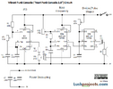
Am playing around building an Atari Punk Console but thinking of adding LEDs that are controlled by 3 band pass filters (low, mid high)
this is for another project for grandson to drive his parents nut with the sound and amuse him with the LEDs.
 

Attachments

  • vibra punk circuit.png
    vibra punk circuit.png
    85.9 KB · Views: 150
  • color organ schematic.pdf
    106.7 KB · Views: 155
Yes? No? Maybe? I don't know. Shrug. Huh?

Now that that's cleared up.

Any bets on upside-down mosfets?
 
Last edited:
I try and follow all the suggestions and going with post#29
For the record, the circuit in post #29 is not my creation. It is merely a schematic for the circuit described in post #12. And the circuit that several people have suggested you follow since then.

But none of the schematics you have posted since post #12 have correctly followed the simple suggested ADD-ON of post #12. If you had, we wouldn't be on post #44 now.

It's my morbid curiosity to wonder about what your schematic looks like currently based on the gibberish since post #29.
 
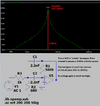
I did a frequency response simulation of the "3kHz Treble Bandpass Filter" from the color organ kit in post #10.
It is not a 3kHz Treble Bandpass Filter, Instead it passes only a 4.8kHz whistle sound.
This filter should pass 3kHz to 20kHz frequencies.

The other two filters are also wrong. The mid filter should pass ALL middle frequencies and the low filter should pass ALL low frequencies, not just a couple of frequencies.
 

Attachments

  • treble filter.png
    treble filter.png
    28 KB · Views: 101
If I am understanding correctly
You need to use P-channel MOSFETs (or PNP transistors) driven from the collectors of the 2N3904s in the original circuit.
is this what the schematic in post@29 doing?
 
It is not a 3kHz Treble Bandpass Filter, Instead it passes only a 4.8kHz whistle sound.
With that much gain it seems to me the "bandwidth" is sort of meaningless. The filter's probably going to rail, so if you took the bandwidth at the 20dB gain level it'd probably work ok for this simple circuit.
 
If I am understanding correctly
You need to use P-channel MOSFETs (or PNP transistors) driven from the collectors of the 2N3904s in the original circuit.
is this what the schematic in post@29 doing?

OMG.

SmartSelect_20230605_142954_Edge.jpg
 
Jameco and you are using slow 1N4002 Rectifier diodes that are used ONLY at 50Hz and 60Hz. I do not know if anybody tested them at audio frequencies. 1N4148 Signal diodes are usually used for audio.

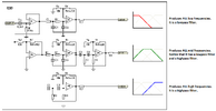
Here is the schematic of 3-way filters that do the filtering you need:
 

Attachments

  • 3-way filters.png
    3-way filters.png
    36.9 KB · Views: 108
Maybe it's best not to redesign the filter stage.

> MrDEB has a video (way back in post #4 I believe) showing the operation of the circuit and he's happy with it.

> Consider the difficulty that "drive the mosfets from the collectors of the pnp transistors" has caused.
 
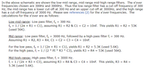
Usually, resistors and capacitors in a filter are calculated for the frequencies you want. In the 3-way filters the frequencies are 300Hz and 3kHz. Here are their components:
 

Attachments

  • 3-way filters components.png
    3-way filters components.png
    34.2 KB · Views: 100

Latest threads

New Articles From Microcontroller Tips

Back
Top