Hi,
I am a complete "noob" when it comes to electonics. I have a 2 part question that I would like to ask the forum. Here is the first part.
I am trying to control the output voltage by a fixed amount. I used a potentiometer for this.
I hooked the source voltage (input) to terminal 1. I grounded terminal 3 and used the wiper (terminal 2) as my output voltage. The source voltage is NOT fixed. It varies from 0V to 5V. The input voltage does not pulsate, it is user controlled. Since I discovered the pot is a voltage divider I could not achieve the desired reults.
eg.
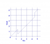
Desired result of 0.25V differential is required on the output voltage. (Please note that this can be any figure between the min and max of input voltage).
IN V ---> OUT V
1 ---> 0.75
1.5 ---> 1.25
2 ---> 1.75
3 ---> 2.75
. ---> .
5 ---> 4.75
Actual result using a pot
IN V ---> OUT V
1 ---> 0.75
1.5 ---> 1.13
2 ---> 1.5
3 ---> 2.25
. ---> .
5 ---> 3.75
Is there anyway I can achieve output voltage by a fixed amount? Please treat me like a 10 year
I am a complete "noob" when it comes to electonics. I have a 2 part question that I would like to ask the forum. Here is the first part.
I am trying to control the output voltage by a fixed amount. I used a potentiometer for this.
I hooked the source voltage (input) to terminal 1. I grounded terminal 3 and used the wiper (terminal 2) as my output voltage. The source voltage is NOT fixed. It varies from 0V to 5V. The input voltage does not pulsate, it is user controlled. Since I discovered the pot is a voltage divider I could not achieve the desired reults.
eg.
Desired result of 0.25V differential is required on the output voltage. (Please note that this can be any figure between the min and max of input voltage).
IN V ---> OUT V
1 ---> 0.75
1.5 ---> 1.25
2 ---> 1.75
3 ---> 2.75
. ---> .
5 ---> 4.75
Actual result using a pot
IN V ---> OUT V
1 ---> 0.75
1.5 ---> 1.13
2 ---> 1.5
3 ---> 2.25
. ---> .
5 ---> 3.75
Is there anyway I can achieve output voltage by a fixed amount? Please treat me like a 10 year