Electro Tech is an online community (with over 170,000 members) who enjoy talking about and building electronic circuits, projects and gadgets. To participate you need to register. Registration is free. Click here to register now.
Welcome to our site! Electro Tech is an online community (with over 170,000 members) who enjoy talking about and building electronic circuits, projects and gadgets. To participate you need to register. Registration is free. Click here to register now.
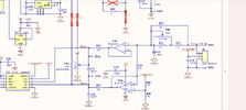
Why do they use half the reference voltage 2.048 on the positive terminal of the U4A op amp to provide a 2.048 reference voltage for the negative terminal of the a/d converter?
Why do they use half the reference voltage 2.048 on the positive terminal of the U4A op amp to provide a 2.048 reference voltage for the negative terminal of the a/d converter?
They actually connect a resistor to each input in+ and in-. Each resistor is connected to an op amp referenced at 2.048v. the Hall+ sensor output snd Hall- sensor feed current through each of those resistors to create a differential voltage input to the ADC. The ADC measures the difference in voltage across the two inputs.
Often it's so you can read negative and positive values, such as if you were sampling an audio signal - otherwise the sampling will only read the positive half cycles.
That's why I'm confused, unless that they are measuring a bipolar sensor. Otherwise, if it reads in only one direction, this set up would not be necessary?
If you Hall sensor is some distance from A/D inputs doing the differential
setup appropriate as it helps get rid of common mode error, noise, IR drops,'
etcc...
But if close then single ended should be OK, although datasheet seems skimpy
covering this.
Keep in mind doing sin gle ended interface your 16 bit converter is now a 15
bit converter as sign bit is always + for your case.
If your Hall sensor has a maximum swing of 4v across the + to - terminals, it is exactly the same if you would
Option A) assume Hall- terminal is at ground and Hall+ terminal is measured, or
Option B) measure the difference of each from 2.048V reference assuming one will be less than 2.048v and one will be equally more than 2.048.
The voltage difference will be the same in option A as in Option B (if, and only if, the output of Hall+ is greater than the output of Hall-).
But, how can Option A handle a negative output from the hall sensor? It can't. The answer is to use Option B to handle both negative and positive outputs from the hall sensor. Center the signal on 1/2V(ref) and all will be good.
A differential amplifier amplifies a difference V, but does not amp a common mode V.
When sensor is far from A/D and say there is a drop in ground buss between A/D
and sensor, of say 1 V, then both A/D inputs would experience the 1 V which does
not appear in output when the A/D amplifies the difference:
Vin+ - Vin- = 1V - 1V = 0.
But if A/D was single ended, say Vin+ = 1V, Vin- = 0V, then V into A/D
= Vin+ - Vin- = 1 - 0 = 1. So ground drop is added to signal being amplified.
By superposition you can figure this out.
Now you cant tell what is sensor value because its all one V. Basically
differential operation eliminates CM voltages from the signal chain, just
leaving the signal in the chain being amped.
If the A/D input is offset such that the sign bit, MSB, never changes, then a
16 bit converter, sign bit being MSB15 (of bits 0 - 15) is irrelevant, so converter
functions as 15 bits.
This site uses cookies to help personalise content, tailor your experience and to keep you logged in if you register.
By continuing to use this site, you are consenting to our use of cookies.