Continue to Site

Welcome to our site!

Electro Tech is an online community (with over 170,000 members) who enjoy talking about and building electronic circuits, projects and gadgets. To participate you need to register. Registration is free. Click here to register now.

  • Welcome to our site! Electro Tech is an online community (with over 170,000 members) who enjoy talking about and building electronic circuits, projects and gadgets. To participate you need to register. Registration is free. Click here to register now.

A solenid latch to contract and release a door after a set amount of time, that is being pulled by a spring to open it.

digandug

New Member
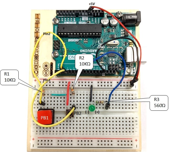
I'm seeking a relatively robust solenoid latch, preferably 12-volt, that can retract after a programmed time interval, such as 20 minutes, upon pressing a trigger button. This action will enable the cabinet door, under constant pull by a spring, to open.

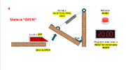
I've provided diagrams illustrating the following states:

  1. The door is closed.
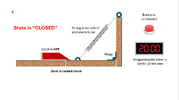
  2. The button is pressed, initiating the timer.
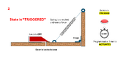
  3. The latch is contracted, allowing the door to open.
  4. The latch returns to its normal state, keeping the door open.
In simpler terms, the circuit will activate the solenoid latch to retract (as shown in image #3) after a predetermined time, delaying the door's opening until the programmed interval has elapsed.

I'm open to suggestions on the easiest method to achieve this. While I understand it can be accomplished with an Arduino, I believe a basic timer might suffice. Please share your insights.


this is not a complicated circuit and its a one off process. meaning it has to be operational over a course of day. the batteries could idealy be over-the-counter type batteries and the solenoid is basic 10 volt from amazon or similar
 

Attachments

  • Screenshot 2024-02-16 231405.png
    Screenshot 2024-02-16 231405.png
    96.3 KB · Views: 73
  • Screenshot 2024-02-16 231705.png
    Screenshot 2024-02-16 231705.png
    90.9 KB · Views: 70
  • Screenshot 2024-02-16 231741.png
    Screenshot 2024-02-16 231741.png
    105.5 KB · Views: 69
  • Screenshot 2024-02-16 231819.png
    Screenshot 2024-02-16 231819.png
    108.2 KB · Views: 64
Last edited:
The abundant push to open mechanisms seem to work as you require. A push button attached to a solenoid should be all that's needed.

Mike.
 
I think you could do the time delay with a CD4020 oscillator/counter as the long period delay, plus a CD4093 quad NAND gate for the start stop, using two gates cross connected as a flip flop (s-r latch) and the other two as a configured to make a monostable for the solenoid active pulse time.

Adds a few resistors and capacitors, plus a start button and power transistor to switch the solenoid current.
 
What are you asking? How to move the latch or how to move the latch after 20 minutes?
thank you for attempting to help me

I aim to design a practical, robust, and reliable circuit that can maybe even operate with regular batteries so I wont have to worry about a complicated power source. this circuit activates a preset timer with the press of a button. Once the preset time elapses, the circuit will trigger the release of a door, allowing it to open. This action involves retracting the solenoid latch, permitting the door to open due to the pulling force of a spring (see pictures)

In simpler terms, the circuit will send an "ON" signal to the solenoid latch after a pre-programmed duration. Consequently, while the door opens, this action is delayed by the specified amount of time previously programmed into the timer.

I am open to exploring Arduino for this project, acknowledging the associated learning curve and cost as my budget of up to $140 US, could allow it.

but I am interested in exploring alternative, potentially simpler, and more cost-effective solutions that others in this field may have utilized previously.

Please confirm if this explanation addresses your inquiry adequately.
 
I am open to exploring Arduino for this project, acknowledging the associated learning curve and cost as my budget of up to $140 US, could allow it.

The Arduino is a micro-controller development system, not an actual device. You could develop your project using one, and then transfer it to a bare chip, such as an AT-Tiny, which is only an 8 pin device.

Likewise you could develop it using a MicroChip PIC, which is available in a range of different 8 pin devices.

Either situation is likely to result in a much smaller, much simpler, and much more capable end result. Timing isn't an issue, and you can easily adjust it from microseconds to years, something very difficult in hardware. It can also be programmed and designed to be VERY, VERY low power.

Minimum component wise - you're looking at one PIC/AVR, one FET to drive relay, one diode across relay, and one button switch to control the device. Plus it's power supply - with a 12V supply a simple 78L05 regulator and two capacitors would be all that's needed.
 
Is this a school project or a work assignment?

Is there a requirement to design a discrete circuit, or is a purchased timer allowed? This sounds like an "ON-delay" timer. Programmable timer modules that cover a 20 minute span are on ebay for around $10.

ak
 
For your design an easy way pf programming is to use block programming, like mBlock .


Basically it takes a GUI representation of your block setup, your design, and converts it
to Arduino code, and programs the board. A Nano board (~3$) would work fine for this :

1708182575142.png


1708182602356.png


The above a first pass at the design, you drag and drop blocks into right hand window,
set any variables needed, and create the control signals on pins.

Use off the shelf relay board, some are isolated, like :


To control solenoids, motors......

If you wanted a wireless networked solution , use Tuniot instead of mBlock, and an ESP8266 or ESP32
board.

Here is what it takes to setup a basic network interface, and you would add the block code,
similar to what I show above, to it to control the door.

1708183472606.png


Lots of fun, easy to learn, many videos on youtube.

Note to use mBlock (its free) your install Arduino IDE (also free) as mBlock uses the Arduino
IDE which has a board programmer mBlock uses to upload the code to the board.

Regards, Dana.
 
Last edited:
For your design an easy way pf programming is to use block programming, like mBlock .


Basically it takes a GUI representation of your block setup, your design, and converts it
to Arduino code, and programs the board. A Nano board (~3$) would work fine for this :

View attachment 144547

View attachment 144548

The above a first pass at the design, you drag and drop blocks into right hand window,
set any variables needed, and create the control signals on pins.

Use off the shelf relay board, some are isolated, like :


To control solenoids, motors......

If you wanted a wireless networked solution , use Tuniot instead of mBlock, and an ESP8266 or ESP32
board.

Here is what it takes to setup a basic network interface, and you would add the block code,
similar to what I show above, to it to control the door.

View attachment 144549

Lots of fun, easy to learn, many videos on youtube.

Note to use mBlock (its free) your install Arduino IDE (also free) as mBlock uses the Arduino
IDE which has a board programmer mBlock uses to upload the code to the board.

Regards, Dana.
Thank you so much. This is great information.
 
There are other block languages, each with different capabilities, but once you
learn one they are all pretty much the same.

Snap4arduino, Scratch, Visuino, Tuniot, Flowcode, Nodered.

A couple of examples :


Regards, Dana.
 
The options given are pretty power hungry.
- How long do you want your batteries to last? Days, weeks, months, years?

- How often will the device be activated? One per hour, day, week, ...

- are the batteries inside or outside of the box? That is, if the batteries fail, will there be a way to access inside of box?

- Do you have info on the specific solenoid latch you plan to use? Current draw and recommended time to trigger are most important.
 
That's why I suggested the CMOS IC option - the standby current can by next to zero; I'd think ~10uA if not less.

I'll try and draw up a schematic tomorrow if I get chance.
A microcontroller solution is tiny consumption as well, certainly insignificant - with battery life being the shelf life of the battery. The only high current issue is the solenoid itself.
 
That's why I suggested the CMOS IC option - the standby current can by next to zero; I'd think ~10uA if not less.

I'll try and draw up a schematic tomorrow if I get chance.
Sorry, I meant "all but the CMOS IC option". You're right that the voltage regulators seem to always make various nano-watt claims overstated.

The 4000-series CMOS IC option is great because no voltage regulation is needed for most battery configurations.

Here is a slightly modified circuit I recently made for someone else.

The power to the op amps is deactivated when the 4017 is latched on a value of "9" as a standby value. It draws 10-12ųA in standby with a 9V battery.

Once the button is pressed to reset the 4017, the op amps become powered through the PNP (2N3906 for example) and the left op amp is a relaxation oscillator. One oscillation every 150 seconds. The 4017's output #8 will be activated in about 1200 seconds (20-minutes).

Since we don't want to waste battery power for a full 120-second step of output #8, we feed that pin into the second op amp. That op amp is essentially a mono-stable and triggers for about 1-second (into the MOSFET gate). The schematic shows a light bulb but any device (including the solenoid latch) can be there.

When the next oscillator step triggers, the 4017 latches into a standby mode and pauses until the next button press. You can play with the 1M resistor at the CP1 pin to try to reduce standby current - but, since you're only consuming a dozen microamps, you should be OK for more than a year (maybe more) on the 9v battery - it depends how often the thing is triggered and the current draw of the latch.

Any rail to rail op amp can be used - it doesn't have to be low-power because the PNP automatically cuts power at the end of 20-minute cycle. An LM358 or similar 2-channel op amp will be fine.

1708293657942.png
 
Last edited:
And it's disadvantages greatly outweigh that :D
Disadvantages if you already know how to download the IDE, write the code, have a programmer for transfer the code to the chip. In those cases, I completely agree.

On the other hand, if someone doesn't want to learn how to code, buy the programmer, upload to the chip, then, 4000-series CMOS ICs have advantages - including 3-18v supply range with no regulator.
 

Latest threads

New Articles From Microcontroller Tips

Back
Top