Electro Tech is an online community (with over 170,000 members) who enjoy talking about and building electronic circuits, projects and gadgets. To participate you need to register. Registration is free. Click here to register now.
Welcome to our site! Electro Tech is an online community (with over 170,000 members) who enjoy talking about and building electronic circuits, projects and gadgets. To participate you need to register. Registration is free. Click here to register now.
If you try to drill first the heat from the drill melts the toner and gums up the drill bit.
Drill after etch and toner removal and the center hole will help you guide the drill.
I agree with Rolf, except I usually drill after etching but before I take the toner off.
If you are working in EAGLE CAD, run the ulp called 'drill-aid' from your ulp scripts. It will make all the holes smaller in the center and much easier to drill.
And dude i am using proteus it is very good software as it also have capability of simulation of the circuit in addition to PCB design.
But I dude I have read somewhere that It is preferable to drill before etching is started because the surrounding copper gives better mechanical strength to round pads around the drilled holes. These pads may be ripped off sometimes when drilling after the board is etched. Another good reason is that the etching after drilling would remove any strands of copper around the edges of the drilled hole.
I learned that it is preferable to snip your component leads before soldering because the stress the cutter puts on the lead degrades the connection. I still snip my leads after soldering, though, as it is a lot more convenient to do it this way. I don't know many people - perhaps there are some - who do it the 'proper' way.
I would build a few boards and try it both ways.
If you over-etch the board, and the traces get undercut, then there is more chance of tearing off a small pad with the drill. Make your pads and traces as large as you can, then they will be sturdier. The boards I make are designed to be made at home. I would use thinner traces, etc. if I were submitting a board to be made commercially.
If you don't have a printer at home, then go to a copy shop and use a photo copier, or have them laser print it. Like 3v0 says, you won't know if your paper - toner works well until you try.
Don't count on your first board turning out a masterpiece. If I remember, my first one was great, until I tried to drill it...
The more boards you do, the more you develop what works - for YOU!
You can test the different papers you have available by printing on it with a copy machine; it must be toner based machine. Your school surly have one available. There is no garranty that the toner of the copier will react excatly like a laser priter but it will be close.
Ordenary B&W printed text is fine for testing.
After printing, cut each sheet up in to at least a dozen pieces so you can test different heats of your iron and your transfer technique.
Then find a friend with a laser printer, he doesn't have to be close by, it can all be done by email and snail-mail. Of cause he as to use the same program for the printing.
It all would be easier if you used a PCB program that is more readily used and free to download, like Express PCB.
I am using proteus 7 professional.It is very good software all in one... I understand that but.....
As I want to use that paper that can release the toner on the copper clad as when heat is applied on it by domestic press......
So can u please enlist the papers that fall in that category ? ...so That i can experiment with it.....
I use P&P but selection of suitable paper has been covered here numerous times, do a search.
Secondly, I want to ask that when I apply heat on paper by press than i think that paper get burn or get brownish due to heat ...is it so ?? The paper should not turn brown! The fusing temperature of HP toner is listed as 200°C so the iron should be around the same temp. But P&P requires only around 300°F, much lower and I don't understand why.
With such problems and the printer shops refusing to do even at % times the normal charge, i felt insulted and went ahead owning HP P1007 laser printer.
Ignorance (India) Unlimited, i used to call these people
I have been trying different methods as per PULSAR
I purchased the Laminator
set the printer to print density 5
warm the laminator for 1/2 an hour before using
use the 5mm setting on the laminator
CLEAN your board with dish soap and a Scotchbrite pad or 600 wet/dry sandpaper
pass the board through about 6 times switching around each time
use the green TFF paper to fill any voids in the print
pass through several times until you can see your circuit traces when you lift up an edge.
remove ink w/ acetone
CLEAN your board with dish soap and a Scotchbrite pad or 600 wet/dry sandpaper again
coat with liquid tin
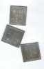
all my traces are .020 except the one between the ic pins =..010
I filled all the unused ares so they wouldn't etch - not needed anyway.
I now need to drill my holes
This site uses cookies to help personalise content, tailor your experience and to keep you logged in if you register.
By continuing to use this site, you are consenting to our use of cookies.