Continue to Site

Welcome to our site!

Electro Tech is an online community (with over 170,000 members) who enjoy talking about and building electronic circuits, projects and gadgets. To participate you need to register. Registration is free. Click here to register now.

  • Welcome to our site! Electro Tech is an online community (with over 170,000 members) who enjoy talking about and building electronic circuits, projects and gadgets. To participate you need to register. Registration is free. Click here to register now.

Need help identifying PCB component

peepermeeper

New Member
Hello,

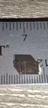
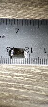
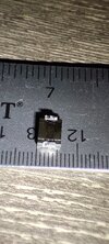
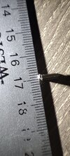
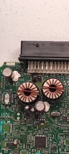
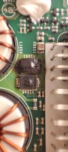
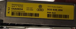
I need help identifying these components Any help would be appreciated. I have an r12 amplifier for a vw passat 2012 fender sound system attached is a picture of all the serial numbers the pair of black boxes with a line that goes down it and is inscribed sc 1a and has a symbol perhaps a switched capacitor? Maybe sg 1a?

Thanks,
Peep
 

Attachments

  • IMG_20230718_194031.jpg
    IMG_20230718_194031.jpg
    2.9 MB · Views: 116
  • IMG_20230718_194459.jpg
    IMG_20230718_194459.jpg
    992.4 KB · Views: 126
  • FLIPPED.jpg
    FLIPPED.jpg
    374.6 KB · Views: 116
Last edited:
I can't identify the components exactly, but I am fairly sure that they are simply diodes.

I think that there are two feeds of +12 V to the module, and each feed is connected to the side of one of those diodes that is away from the inlet connector, and connected to the anodes of the diodes. The cathodes are connected together, and that voltage is used to run the control part of the module, but not the power parts.

That allows the control part to run if either power feed is working. My guess is that the power after the diodes goes to the switch mode regulators that are the other side of the big toroidal inductors.

You can check the continuity between the cathodes and the power feeds of the module. If they don't connect, I've got it wrong.

You can probably use just about any rectifier diode in that package.

However, that doesn't explain why the diodes fail. It's clear that both are damaged. One is worse than the other but that could simply be a slightly different voltage on the two feeds to the module. Either diode would be rated to take the full load current for the control part of the module.

When the diodes have been replaced, if something else has gone wrong in the module, it will take an excessive current when powered up. It could be that there was something connected incorrectly outside the module that ended up taking too much current, in which case the module might be fine, except for the diodes. A fault on the parts after the switch mode power supplied wouldn't caused the diodes to burn.

I suggest you check the continuity as I may have the wrong idea about what the diodes do. If they are in the power supply to the control parts, change them, and power the module from a current limited supply, limited to half an amp or so. Obviously you won't be able to run the power parts under those conditions, but you should be able to see if the circuit functions.
 
I don't think that it's an S1G from Vishay, because the S1G is a lot thinner than it is long. The width of the S1G is 56% to 70% of its length, while the item in the photo has a width that is 93% of its length.

However it could be something similar and I suspect that many types of diode would work.
 
Thanks everybody for the help. If I found a product that fit the dimensions for the mounting pads and general body shape and space how would I know which diode specifications to choose. Attached is one I found that's form factor very closely matches the original.
 

Attachments

  • 2103231734_Vishay-Intertech-S5M-E3-57T_C554010.pdf
    96.7 KB · Views: 111
  • IMG_20230719_214138.jpg
    IMG_20230719_214138.jpg
    1.4 MB · Views: 102
  • IMG_20230719_214211.jpg
    IMG_20230719_214211.jpg
    1.5 MB · Views: 118
  • IMG_20230719_214234.jpg
    IMG_20230719_214234.jpg
    1.6 MB · Views: 104
  • IMG_20230719_214612.jpg
    IMG_20230719_214612.jpg
    1.5 MB · Views: 100
Last edited:
The specification probably doesn't matter. The voltage rating must be more than 12 V, but the lowest rating you can get is probably 50 V. The original may be a higher voltage as that doesn't make it more expensive in practice.

The current rating will be similar in a replacement because it is much the same size as the original, and in an application like that the rating was probably generous.

The most important thing is to have a current limited supply when you connect up. If not there is a big risk of the real fault blowing the diodes again.
 

Latest threads

New Articles From Microcontroller Tips

Back
Top