Continue to Site

Welcome to our site!

Electro Tech is an online community (with over 170,000 members) who enjoy talking about and building electronic circuits, projects and gadgets. To participate you need to register. Registration is free. Click here to register now.

  • Welcome to our site! Electro Tech is an online community (with over 170,000 members) who enjoy talking about and building electronic circuits, projects and gadgets. To participate you need to register. Registration is free. Click here to register now.

pcb board recover help

baristini

Member
Hello to everyone.

I have a pcb board that stoped to work. I can find the problem...

Can anyone help me the to find the fault?

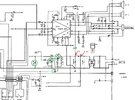
In attach i have the schematic of the board.

When conecting the board to power (9.5volt) i get power (9.5V) before D1 diode, but 0V after this diode.

Already replaced this diode and same result.
Disconected TR8 TR9 and LA4700 ( pins 14 and 5 ) and still have the same result....
TR8 and TR9 seem good. Replaced also LA4700 amp.

if someone have a clue or test to perform please let me know...

Thanks all!
 

Attachments

  • schematic.jpg
    schematic.jpg
    156.8 KB · Views: 68
  • yamaha_psr-400_psr-500.pdf
    2.7 MB · Views: 153
Solution
Thanks a lot for your help!!

It's already working.

In standby state TR8 is off.

When you press the on/off button then the TR9 turns high, causing the TR9 to go hight too, powering the entire PCB.
Thank you so much for your help. Have a great weekend!
Hi, welcome.
Make sure your power adapter is capable of making anything else 9V to work. (like a light bulb)

Disconnect any one component (or trace) fed by the trace at the cathode of D1. Example, that electrolytic capacitor next to D1 and probe again. Then, choose another branch or component fed +V by that trace; and probe for voltage. Continue until the circuit that when disconnected, restores +9V

Come back with findings.
 
Are you sure that you get a reading of +9.5 volts at the anode of D1 ? (You just say that you get 9.5 volts but you do not say if this is positive or negative.) Diodes normally fail short circuit unless the input current is high enough to blow them open circuit. As you seem to have a coaxial input connector it seems unlikely that the power supply could provide enough current to blow the diode open circuit, I suspect that you are using a different power supply to the original and the connector polarity on you new power supply is wrong.

Les.
 
There's almost nothing that cause the fault you report - other than the diode if O/C - if you've replaced it and it's still the same, make sure you haven't put it in backwards. Other wise there's a S/C to ground after the diode, and the new diode has gone O/C instantly.

Almost everything you're checked was pointless, as Les suggested, are you using the wrong power supply?, with reversed polarity? - and is the voltage on D1 negative or positive?.
 
The battery port is 6x1.5=9V is in parallel reading 0V. So there appears to be a short circuit that may be traced with a suitable tester.
 
When conecting the board to power (9.5volt) i get power (9.5V) before D1 diode, but 0V after this diode.
As others have said, the PSU appears to be the wrong polarity.

The majority of small PSUs have the centre contact positive, which is what that keyboard requires.

You are using a 9V supply - is that one for a guitar pedal? Those are almost all negative centre contact!
 
Are you sure that you get a reading of +9.5 volts at the anode of D1 ? (You just say that you get 9.5 volts but you do not say if this is positive or negative.) Diodes normally fail short circuit unless the input current is high enough to blow them open circuit. As you seem to have a coaxial input connector it seems unlikely that the power supply could provide enough current to blow the diode open circuit, I suspect that you are using a different power supply to the original and the connector polarity on you new power supply is wrong.

Les.
ill check that! in fact im powering a 9v yamaha with a roland PS.... i have to check polarities!! Thx
 
As others have said, the PSU appears to be the wrong polarity.

The majority of small PSUs have the centre contact positive, which is what that keyboard requires.

You are using a 9V supply - is that one for a guitar pedal? Those are almost all negative centre contact!
I'm using a PS from a roland RD300sx ( 9v ). I'll check tomorrom polarity!! Thx!
 
I would not put full power into a known short circuit. I would hope you have the correct polarity.

Rather consider a small digital lab supply with a current limiter and use a low voltage to see if the resistance is linear. ($50 Banggood or more) e.g. https://www.banggood.com/RIDEN-RK60...html?cur_warehouse=CN&ID=6323591&rmmds=search

Using a digital readout on a lab supply, you can measure V, I, and adjust for CC or CV mode and display P (Watts) and measure milliohms changing depending on the path length and conductor size..
 
Last edited:
If the current measured in #11 was 5A at 0V, then no heat is expected. If it was 1V then something should get warm up fast.

Use a better test at low voltage for continuity shorts with a more sensitive DVM.
 
D1 is reverse polarity protection. If you bypassed that with the wrong supply polarity, it may have damaged the audio amp or other components.

It was probably the amp IC taking all the current.. It's probably near short-circuit with the wrong polarity connected.
 
I have to check if im using wrong PS... but i injected 9.5V after diode D1 and i read 5Amp consume on multimeter... Does this current is acceptable?
You've still never mentioned what polarity you're connecting anything - it's likely you've connected it the wrong way and blown things - as other have said, the diode is for reverse polarity protection, if you've bypassed it and applied -9.5V instead of +9.5V then you've probably caused considerable damage.
 
I agree with rjenkinsgb that the power amp (IC 22) is the most likley causeof the short. I suggest cutting the track between D1 cathode and pin 4 of IC22 at a point where you can repair it by soldering a piece of wire across the cut.
Before cutting the track measure the resistance between D1 cathode and power ground. I suspect you will get a reading of close to zero ohms. If you do get a very low reading then you can make the measurement after cutting the track to see if the short has cleared. This saves the risk of doing more damage by aptying power from a low impedance source.

Les.
 

Latest threads

New Articles From Microcontroller Tips

Back
Top