Continue to Site

Welcome to our site!

Electro Tech is an online community (with over 170,000 members) who enjoy talking about and building electronic circuits, projects and gadgets. To participate you need to register. Registration is free. Click here to register now.

  • Welcome to our site! Electro Tech is an online community (with over 170,000 members) who enjoy talking about and building electronic circuits, projects and gadgets. To participate you need to register. Registration is free. Click here to register now.

Hobby audio player project noise problem

huseyin34

New Member
Hi everyone,

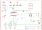
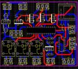
I'm new in here. I designed a controller card project and the card can switch some devices with relays, dfplayer mini to play sounds from sdcard, external bluetooth music player card is connected to the circuit. cd4066 used for audio switching between dfplayer and Bluetooth audio. But there is noise in audio. 12volt power supply is used with 7805 regulator. Bluetooth Audio and amplifier also uses same power sources from the board. But I have noise in the sound. Can you please review my circuit ?
 

Attachments

  • Schematic_somine_pcb_v1.3_2023-11-30.png
    Schematic_somine_pcb_v1.3_2023-11-30.png
    126.4 KB · Views: 99
  • IMG_20231130_004630.jpg
    IMG_20231130_004630.jpg
    266.9 KB · Views: 118
It looks like the PCB does not have a ground plane?? If that is the case, the AMP & BT connectors do not appear to have their grounds linked to the rest of the circuit grounds?
That's going to cause a serious noise problem, as the amp inputs are effectively floating.


For info, the 4066 only works really well near mid-supply. For best operation with audio, the signals should all be capacitor coupled, with each signal having a high value resistor (eg. 47K or 100K) to mid supply voltage as the 4066 side of the cap.

You can eg. use two 1K resistors in series across the supply, with a cap from the mid point to ground, to give the mid-supply bias.

That also pretty much eliminates any switching clicks or thumps, as there are no DC level changes as the switches operate.

Thanks. I will consider your valuable comments.
 
Another couple of things - I just noticed the circuit does not show any flywheel diodes across the relay coils? Unless the relays have those built in, it can damage whatever is driving the relays.

To minimise any hum, connect the amp power negative/ground and PSU negative at your PCB power terminal; don't take the amp negative separately to the PSU, as there can then be different voltage drops on the wires, which will get added in to the audio going to the amp.
 
The ESD diodes internal to the CD4066 may be rectifying the audio with a single supply and audio at 0Vdc. Bad idea. It must be bipolar supply or AC coupled to 2.5V.

Although the uC port is not intended to drive a 5V relay, it doesn't need a flyback diode as the Pch will absorb the turn0off current.
 
It looks like the PCB does not have a ground plane?? If that is the case, the AMP & BT connectors do not appear to have their grounds linked to the rest of the circuit grounds?
That's going to cause a serious noise problem, as the amp inputs are effectively floating.


For info, the 4066 only works really well near mid-supply. For best operation with audio, the signals should all be capacitor coupled, with each signal having a high value resistor (eg. 47K or 100K) to mid supply voltage as the 4066 side of the cap.

You can eg. use two 1K resistors in series across the supply, with a cap from the mid point to ground, to give the mid-supply bias.

That also pretty much eliminates any switching clicks or thumps, as there are no DC level changes as the switches operate.
for coupling what type of capacitor should i use ? and value of it ?
 
Then 100k to 5V and 100k to 0V gives Req= 50k and with 10uF T=RC= 0.5 s.

The sound will still pop switching channels charging up the caps, so DC couple +/-5V is better but then logic levels won't work unless you use a better CMOS switch made for bipolar switches.
 

Latest threads

New Articles From Microcontroller Tips

Back
Top