Electro Tech is an online community (with over 170,000 members) who enjoy talking about and building electronic circuits, projects and gadgets. To participate you need to register. Registration is free. Click here to register now.
Welcome to our site! Electro Tech is an online community (with over 170,000 members) who enjoy talking about and building electronic circuits, projects and gadgets. To participate you need to register. Registration is free. Click here to register now.
Don't really understand but the circuit had odd behavior for about 10 minutes then cleared up.
Started not responding to the button then when it finally tripped the relay I began timing how long it would take before I could manually turn it off. There was no pattern. Between 30-90 seconds. That went on for about 5 minutes then it suddenly started functioning as designed. With the following exception.
When the timer has expired the corresponding led goes out but the relay remains latched. Pressing the button then releases the relay.
The only thing I notice it works as a pulse or a latch but on latching it will not shut off upon un-latching. I can configure the touch switch to pulse but I have some switches that latch by means of a micro switch that is activated when the cupboard door is opened. Im going to scour the web looking for a solution.
Don't really understand but the circuit had odd behavior for about 10 minutes then cleared up.
Started not responding to the button then when it finally tripped the relay I began timing how long it would take before I could manually turn it off. There was no pattern. Between 30-90 seconds. That went on for about 5 minutes then it suddenly started functioning as designed. With the following exception.
Sounds like loose connections. Try reseating components around the 555. But I'd like to focus on a single functional block at a time. Make sure the 4013 is working consistently as intended first.
When the timer has expired the corresponding led goes out but the relay remains latched. Pressing the button then releases the relay.
The only thing I notice it works as a pulse or a latch but on latching it will not shut off upon un-latching. I can configure the touch switch to pulse but I have some switches that latch by means of a micro switch that is activated when the cupboard door is opened. Im going to scour the web looking for a solution.
The input needs to be a positive going signal (low to high) to trigger the input circuit. If the input signal latches high, it wont trigger when the signal goes low. Thats the way it is designed. It will trigger the circuit when the signal goes high again, after going low.
We'll need to modify the input circuit to handle the second condition and trigger the circuit when a micro switch signal changes from high to low. That's not an issue
Currently, my bench circuit works consistently like you want. When I press the button, the relay (I'm using a load resistor) energizes. If I press the button before the 555 times out, the timer is reset and the load resistor de-energizes. If I dont press the button, then the load resistor de-energizes when the 555 times out. If I press the button again, the cycle repeats as designed.
I'll compare your schematic with the original schematic in the morning. I'll also modify the input to trigger on a high to low signal. We'll probably need two different types of input circuits.
This is all so fascinating. Im excited to see this through. I had difficulty with my last project too. The BB version worked fine but the soldered up product would not work. I checked it over and over for a few days. Then all of a sudden I power it up and it worked. I made a second one and it did the very same thing. The just like the first one started working.
This morning I checked each leg on each chip. I traced all the jumpers. I powered it up. There was some hesitation getting it to work but it does function just as it did last night. I can manually operate it but if I let it time out the led at pin 10 goes out but the relay stays latched.
Some other things that might help pinpoint an issue. The buzzer only chirps for a millisecond and the led im using to visually show that the relay closed is dim. It has the same 150r resistor as the others. Food for thought.
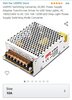
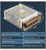
Lets make sure the power supply is not "limiting" and starving the circuit of current.
Your gonna need at least a 5v, 300mA supply. A 5v, 500mA is preferred.
Ok. I looked up the part number on the module. The specifications say it is an adjustable DC-DC converter. So the input you mentioned should be 12v DC (not a transformer I hope). A 12VDC wall wart will work. The output should be adjusted to 5.5 VDC. Did you make the output adjustment?
MP2307 DC-DC 3A Mini Step Down Adjustable. 4pc MP2307 DC-DC Converter adjustable Step Down module. Output Current: Rated Current 1.8A (3A MAX, can not be prolonged). Non-isolated Step-Down module (BUCK).
Sorry. To me transformer / power supply are one in the same. But I am learning they are NOT. So yes the Ledmo power supply 12v. With this mini-360 attached to its output and diald down to 5.5v
This site uses cookies to help personalise content, tailor your experience and to keep you logged in if you register.
By continuing to use this site, you are consenting to our use of cookies.


")