Electro Tech is an online community (with over 170,000 members) who enjoy talking about and building electronic circuits, projects and gadgets. To participate you need to register. Registration is free. Click here to register now.
Welcome to our site! Electro Tech is an online community (with over 170,000 members) who enjoy talking about and building electronic circuits, projects and gadgets. To participate you need to register. Registration is free. Click here to register now.
Did you turn your PNP transistors over? To turn the PNP transistors OFF, you need to drive their bases higher than V1-Vbe...+5V-0.6V...~+4.5V. +3.3V will turn the NPN transistors ON, but not turn the PNP's OFF. You need to do that the get 5V across the coil.
Not sure where your priorities are if you are talking mass production. A 2-coil latching relay, 2 resistors, and 2 transistors, would seem cheaper. Are you stuck on this design for some reason...like...no,I won't go there.
I cant use a dual coil because it consumes 2W, 5V (each coil), and my 5V regulator cant push 400mA.
My 1 coil relay can be switched with only 75% of 5V = 3.75V @ 267mA.
Is it possible to switch off the PNPs now that you know it can consume only 3.75V (with 267mA)?
Thanks.
- 5V comes from 5V regulator which can push up to 300mA current.
- 3.3V comes from MCU GPIO pins which can push up to 20mA.
- low cost and low power consumption driver.
- 5V comes from 5V regulator which can push up to 300mA current.
- 3.3V comes from MCU GPIO pins which can push up to 20mA.
- low cost and low power consumption driver.
I would like to switch up to 16Arms loads.
I would like that the relay would consume 1W when switched, and minimum voltage drop of 3.75V @ 267mA, or maximum voltage drop of 5V @ 200mA.
I would like the relay driver to be as low cost as possible (demand of head of crew).
Addition:
How did you and KMoffett reach the conclusion that VB > 4.5V?
VEC,sat < 0.4V
VEB, on < 1.3V
VCB < VCB,on,max
The way i see it, smaller VB means that both junctions (EB & CB) will be in forward state => staturation state.
To get around the voltage drop of two transistors use logic level FETs but you'll still need 3v to 5v level converters to get those fets to switch on & off. FETs also make good level translators. So 4 n & 2 p channel FETs and a few pull up resistors should cover it.
1. The relay must consume at least 75% of 5V in order to change its state, how come that its coil's voltage (that shouldn't change after switching) was less than 1V?
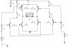
Assuming your second schematic is what you built and the right side has +3.3V applied and the left side 0V, Q4 and Q2 are both "turned on" which is wasting power by tending to short out the +5V supply. The voltage at the right side of the relay will be somewhere between 1.6V and 3.4V, depending greatly on the particular transistors personalities (characteristics), as the 5V is voltage divided between them. The left side of the relay will have somewhere around 4V because Q3 is also turned on. With 4 volts on the left side and 1.6-3.4V on the right side, you can see why the relay coil only has about 1 volt on it.
2. Another problem that occured was that when both inputs V1,V2 were 0V, the current from the 5V PSU was 50mA.
It means that the current were flowing from the PNP collector to the base? Should it happen?
With both inputs at 0V, Q3 and Q4 are turned on, the base current of each of those transistors being 23 mA, for a total of 46 mA. (5V-0.6V)/190 ohm= 23 mA. 0.6V is the base-emitter voltage.
Assuming your second schematic is what you built and the right side has +3.3V applied and the left side 0V, Q4 and Q2 are both "turned on" which is wasting power by tending to short out the +5V supply. The voltage at the right side of the relay will be somewhere between 1.6V and 3.4V, depending greatly on the particular transistors personalities (characteristics), as the 5V is voltage divided between them. The left side of the relay will have somewhere around 4V because Q3 is also turned on. With 4 volts on the left side and 1.6-3.4V on the right side, you can see why the relay coil only has about 1 volt on it.
With both inputs at 0V, Q3 and Q4 are turned on, the base current of each of those transistors being 23 mA, for a total of 46 mA. (5V-0.6V)/190 ohm= 23 mA. 0.6V is the base-emitter voltage.
Yes, there is a problem. You need more than 3.8V at the base of T6 to turn T1 off. 5V minus the BE voltages of T1 and T6 equals 3.8 volts. Your 3.3 volt input isn't going to get you that.
Can you use diodes or more of the same transistors. I don't know what the constraints are what parts you have to work with.
I would like to switch up to 16Arms loads.
I would like that the relay would consume 1W when switched, and minimum voltage drop of 3.75V @ 267mA, or maximum voltage drop of 5V @ 200mA.
I would like the relay driver to be as low cost as possible (demand of head of crew).
None of your requirments make any sense.
You have got to stick with my line of thought.
What have you provided in your first discussion is an "H-bridge" An H-bridge is designed to deliver a voltage (and current) to a load in one direction (and then in the opposite direction). It is mainly designed to drive a MOTOR in forward and reverse direction. This is not what you want.
What do you want to do?
I assume you want to operate a relay from the output of a microcontroller.
This is a very simple requirement.
How many times per second do you want the relay to be activated?
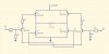
Using the same number and type of components as in your latest design, the attached circuit will work. You should optimize the resistor values for the greatest margin and performance with your transistors.
The circuit is very similar to the Collin55 motor circuit with a few tweaks for two inputs instead of one so you can turn all transistors off.
That could be a great idea.
Before we go to the next level (adding parts which make the design to cost more - we wanna go for mass prodution), i really want to understand what is wrong with this design, why the relay's voltage wasn't around 5V, and why was the stand-by current 50mA and not less?
To turn a PNP off, the base voltage needs to be at least as positive as the emitter. You only have 3.3V on the base of Q4, while the emitter is at 5V. Under this condition, Q2 and Q4 will both be on, and Q4 will most likely will die due to excess power dissipation. In your simulation, try probing the currents in Q2 and Q4.
The collector of Q3 should be near +5V. I don't understand why it is at 582.4mV.
Using the same number and type of components as in your latest design, the attached circuit will work. You should optimize the resistor values for the greatest margin and performance with your transistors.
The circuit is very similar to the Collin55 motor circuit with a few tweaks for two inputs instead of one so you can turn all transistors off.
Thank you so much!
I simulated your design now, and received (with BSR14 NPN, and BSR15 PNP) V_Relay = 4.883V and I_Relay = 188.7mA (0.89W) which is great.
I would like to ask you please :
1.Basically, my relay needs 1W comsumption to change state, and currently it consumes 0.89W.
Is there anyway to increase the current so it would consume 1W?
2. When both inputs are 0V, then the 5V regulator outputs 1.55A, and my 5V regulator can only push up to 300mA. Does it mean that the stand-by mode of this driver is when both inputs are 3.3V?
The problem with that is i'll insert my MCU into sleep mode, then i'll have no 3.3V inputs.
I would like to switch up to 16Arms loads.
I would like that the relay would consume 1W when switched, and minimum voltage drop of 3.75V @ 267mA, or maximum voltage drop of 5V @ 200mA.
I would like the relay driver to be as low cost as possible (demand of head of crew).
None of your requirments make any sense.
You have got to stick with my line of thought.
What have you provided in your first discussion is an "H-bridge" An H-bridge is designed to deliver a voltage (and current) to a load in one direction (and then in the opposite direction). It is mainly designed to drive a MOTOR in forward and reverse direction. This is not what you want.
What do you want to do?
I assume you want to operate a relay from the output of a microcontroller.
This is a very simple requirement.
How many times per second do you want the relay to be activated?
I dont want to switch the relay oftenly, a few times in a day (on and off).
I would like that the stand-by mode of the driver will be when both inputs are 0V, so i could insert my MCU into sleep-mode.
Using the same number and type of components as in your latest design, the attached circuit will work. You should optimize the resistor values for the greatest margin and performance with your transistors.
The circuit is very similar to the Collin55 motor circuit with a few tweaks for two inputs instead of one so you can turn all transistors off.
A potential problem with this design is it raises the voltage on the I/O pins of the microcontroller above the chip's Vcc. See **broken link removed**.
This site uses cookies to help personalise content, tailor your experience and to keep you logged in if you register.
By continuing to use this site, you are consenting to our use of cookies.

")