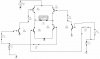
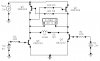
Alphadog, see the attached. It will not harm your I/O. In sleep mode your I/O retains the mode and state that is set before entering sleep mode. At power-up, your I/O is set to input mode with no pull-ups, so all bridge transistors will be off. You should put reversed biased diodes across each of the four transistors to protect the transistors against counter-EMF from the relay coil when it is turned off.

")