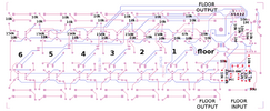
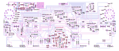
I'm working on a project which involves some old conference interpreter consoles from around 2008. They were designed to work with seperate distributor boxes into which you plug a floor signal from the venue PA system and it passes that to all the consoles. In return, the consoles pass their interpreted audio back to the distributor boxes as six seperate audio signals so that they can be output to transmitters. The problem is that there are only a few working distributor boxes left, and their use is quite limiting in terms of the configurations possible. For this reason I have been modifying the consoles to have their own outputs, and make it possible to input the floor signal without the distributor boxes.
On the whole, everything is working great, but the floor input, the most import element, is not working. With the majority of consoles, no floor signal can be heard, even though it is definitly there, however it does work on some of the consoles, although not necessarily all of the time. All the other channels work fine, but the consoles clearly do something a little diferent with the floor signal.
My conclusion is that there is some kind of impedence mismatch. If I play with the levels from the floor mixer (all around line level) I can sometimes hear something on some of the consoles, although it goes from very faint or non existent, to totally distorted, with no middle ground. It's odd because on a small number of the consoles, it just works. I do know that over time, some modifications were made to the consoles, including changing some resisters on the mic pre-amp to boost gain, but I don't see that this impacts on the floor signal, and besides, the consoles that work seem to include boosted and non boosted - I can not establish a pattern.
So, my question is this, how do I modify the input from floor in order to better match whatever the consoles expect? I am thinking either a mod to every single converted console so that the signal is 'corrected' immeadiately after the floor input jack, or a box or special cable that sits between the floor mixer and the console the floor signal is brought into.
I've tried a 600ohm 1:1 transformer with center taps configured to provide what I imagine is 2:1, and it kind of worked, briefly, on one console. Not exactly a definitive solution. I also tried what I think is an L-pad using a variable resister but is was a 22k ohm pot and I suspect that it well beyond the range needed. I know next to nothing about impedense matching. I also don't know how to measure the input and output impedences of the existing kit, and to make it even harder, I don't currently have access to a working distributor box as they are in short supply and needed for events.
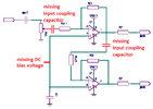
Update: As well as the transformer and half hearted attempt at an L-pad, I also tried putting the floor through a 5532 based amp before putting it into the consoles. This was interesting because it worked, kind of, for a bit, although with lots of hum. I assumed the hum was power supply related and tested that by disconnectiong the power to the amp. The noise did not go away but interestingly the audio remained , although quieter. It appears the insertion of the amp provided the required impedence match, to a degree, regardless of it being an active circuit. More confusion mostly.
Any advice?
p.s. I have schematics of both the consoles and distributors.
On the whole, everything is working great, but the floor input, the most import element, is not working. With the majority of consoles, no floor signal can be heard, even though it is definitly there, however it does work on some of the consoles, although not necessarily all of the time. All the other channels work fine, but the consoles clearly do something a little diferent with the floor signal.
My conclusion is that there is some kind of impedence mismatch. If I play with the levels from the floor mixer (all around line level) I can sometimes hear something on some of the consoles, although it goes from very faint or non existent, to totally distorted, with no middle ground. It's odd because on a small number of the consoles, it just works. I do know that over time, some modifications were made to the consoles, including changing some resisters on the mic pre-amp to boost gain, but I don't see that this impacts on the floor signal, and besides, the consoles that work seem to include boosted and non boosted - I can not establish a pattern.
So, my question is this, how do I modify the input from floor in order to better match whatever the consoles expect? I am thinking either a mod to every single converted console so that the signal is 'corrected' immeadiately after the floor input jack, or a box or special cable that sits between the floor mixer and the console the floor signal is brought into.
I've tried a 600ohm 1:1 transformer with center taps configured to provide what I imagine is 2:1, and it kind of worked, briefly, on one console. Not exactly a definitive solution. I also tried what I think is an L-pad using a variable resister but is was a 22k ohm pot and I suspect that it well beyond the range needed. I know next to nothing about impedense matching. I also don't know how to measure the input and output impedences of the existing kit, and to make it even harder, I don't currently have access to a working distributor box as they are in short supply and needed for events.
Update: As well as the transformer and half hearted attempt at an L-pad, I also tried putting the floor through a 5532 based amp before putting it into the consoles. This was interesting because it worked, kind of, for a bit, although with lots of hum. I assumed the hum was power supply related and tested that by disconnectiong the power to the amp. The noise did not go away but interestingly the audio remained , although quieter. It appears the insertion of the amp provided the required impedence match, to a degree, regardless of it being an active circuit. More confusion mostly.
Any advice?
p.s. I have schematics of both the consoles and distributors.
Last edited: