Continue to Site

Welcome to our site!

Electro Tech is an online community (with over 170,000 members) who enjoy talking about and building electronic circuits, projects and gadgets. To participate you need to register. Registration is free. Click here to register now.

  • Welcome to our site! Electro Tech is an online community (with over 170,000 members) who enjoy talking about and building electronic circuits, projects and gadgets. To participate you need to register. Registration is free. Click here to register now.

Positive / Negative voltage circuit problem

Jayr

New Member
Hi, everyone. I do hope that this is the right place to post, if not i will remove it.
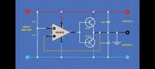
My problem is that i am trying to build this circuit (picture attached). At first when i built it on a breadboard, it worked perfectly but the moment i moved it to vero board it gives only negative volttage. At the voltage divider it measure 4 volts with a total supply of 6v. So it gives only - 6 volts Both transistors are testing okay also. And i am using a TL062 op amp, everything as described in the picture. It simply won`t work. Can somebody please give some advise? I want to add it to my psu as a means to get dual voltages.
 

Attachments

  • Pos_Neg_Volt.jpg
    Pos_Neg_Volt.jpg
    472.5 KB · Views: 70
You likely have a wiring error or part connected incorrectly.
Double check all you wiring, and the pinout of the op amp and both transistors.
 
Hi, Crutchow. I've been doing that for the last hour or so but i need to add that I'm not as experienced. Just beginning to learn all by myself. I will, however take a look at thise again. I will have to do it tomorrow since its almost 9 pm here. Thanks for responding so quickly. I really appreciate it.
 
Hi, Nigel. I think you might be spot on with regards to the resistor since my voltage divider is supposed to give me 50% of the total supply which it does not. Its almost 10 pm here in SA. Can i do that in the morning? Not sure what time it'll be over there, though.Thanks for the advise in the meantime.
 
Hi, Nigel. I realised you guys are trying to hell and the least i can before bed is send the pics. I hope they were taken the right way Btw i am using an mc34071 op amp because of the greater supply voltage. I was using the tl062 on the breadboard. Thank you for your time. I get back early in the morning.
 

Attachments

  • 17098408645452004342639217512451.jpg
    17098408645452004342639217512451.jpg
    665 KB · Views: 64
  • 17098409081872341678239379464401.jpg
    17098409081872341678239379464401.jpg
    2.1 MB · Views: 66
For the MC34071, if Vcc is only 6V then the common mode input voltage range is about 0V-4V and the opamp output voltage is limited to about 0.1V-5V. You will lose at least another 1.4V in the external output transistors.
 
1709868703694.png


Red squares - possible solder whiskers between tracks.

Blue squares - what are the big solder blobs for?
Trying to solder to the enameled wire?
Don't try to use enameled wire for the jumpers, just use tinned wire like the white wire but with the insulation removed.
Making a reliable joint will be much easier.

JimB
 
Morning, all. Yes i tried to cover the wire with those dolder blobs. I will look at those tracks and if needed i will redo the whole circuit with the tinned wire and let you know. Thanks a lot in the meantime.
 
Most of you solder joints have too much solder, and look like they could be cold (no connection).
You should be able to see the outline of the wire being soldered.
This is how to make a proper joint. and how it should look:

1709919788193.png
 
You don't appear to have cut any of the tracks between the Op-amp pins!
Morning, SarahMCML. You are so right! I don't know how i could have forgotten about that one. Usually the first thing i do. Wow. Haven't noticed it myself untill now. That's probably it. I was just about to start a new board, got all the stuff ready but i will first see to this issue and report bact to you guys. Thanks again.
 
Most of you solder joints have too much solder, and look like they could be cold (no connection).
You should be able to see the outline of the wire being soldered.
This is how to make a proper joint. and how it should look:

View attachment 144874
This is also worth bearing in mind. I'll print this one out and paste to the wall in full view.
 
Hello, all. I just want to thank all off you who helped and gave advice with the problem i had. I started a fresh board and built it with all that you told me in my mind. And lo and behold, my circuit functions perfectly as you can see in the attached pictures. Thank you all so very, very much. You guys are just great!!!!
 

Attachments

  • 20240325_183526.jpg
    20240325_183526.jpg
    2 MB · Views: 38
  • 20240325_183538.jpg
    20240325_183538.jpg
    1.9 MB · Views: 37
  • 20240325_183543.jpg
    20240325_183543.jpg
    1.6 MB · Views: 41
  • 20240325_183550.jpg
    20240325_183550.jpg
    2.4 MB · Views: 47
It is good to hear a success story, thank you for the feedback.

JimB
 

Latest threads

New Articles From Microcontroller Tips

Back
Top