Continue to Site

Welcome to our site!

Electro Tech is an online community (with over 170,000 members) who enjoy talking about and building electronic circuits, projects and gadgets. To participate you need to register. Registration is free. Click here to register now.

  • Welcome to our site! Electro Tech is an online community (with over 170,000 members) who enjoy talking about and building electronic circuits, projects and gadgets. To participate you need to register. Registration is free. Click here to register now.

how should you design milliohm meter using dvm display

Flashdrive34

New Member
HI TO ALL MEMBERS:


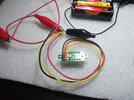
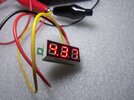
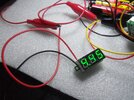
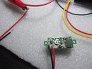
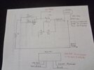
I was working on milliohm tester and needed a 200mv meter. So I purchased one of these 3 digit digital voltmeters and wanted to change it to 200mv meter or 300mv meter. Which ever would work to get it to 200mv or 300mv meter. With one meter I purchased it is 3 wire red is vcc black vdd and yellow is measure. You read from 0 to 30v full scale. Beyond 30v will destroy dvm. I also ordered 200mv meter from china which should be here in a month or less. I ordered few more dvm from ebay and case I could make work for my tester. It seems like these meters either use a 14 pin ic chip as adc or mcu for this meter. Does any one know how I can convert this meter to 200mv or 300mv full scale? Parameter

Dimensions(L * W * H): 30 * 11.7 * 9.2 mm
Opening Size: 23 * 10 mm
Display Type: 0.28" Red LED Tube
Measurement Range: 0-100V DC
Measurement Rate: ≥200ms/time
Power supply: DC 3-30V
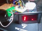
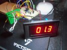
Its a nice little meter thats why I would like to use it for my tester. Thanks for any help you can give me. Since I am 75 years old now guess I should give up on making testers. I wanted see if could use it to find dead shorts on circuit boards. Thanks for any help guys.
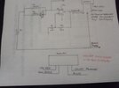
 
If it's a module like this:

DSN-DVM-368_Module.jpg


the solder bridge jumpers at the top left connect different combinations of resistors at the input:

DSN-DVM-368_Schematic.jpg


If you clean up the solder and use the top of the jumper position as input, that should connect directly to the MCU input, so something under 5V for maximum reading,

You can the then add a single supply opamp before the meter, configured for non-inverting x10 to x20 (adjustable) gain, and calibrate it to read millivolts.

eg. This type of configuration, with R2 as a preset resistor for gain calibration; possibly 1K for R1 and a 10K preset plus a fixed resistor for R2?

Opamp_Non_Inverting.png


I'd also add a pair of parallel back to back diodes between the opamp non inverting input and 0V, with a 10K series resistor to that from the input probe wire, to reduce the risk of damage from static or higher voltages,
 
what type of op amp would you suggest ? It would have to be more then plain 741 op amp. I have not used op amp for years so whats a good one? Your answer was great thanks. I am using led displays from ebay and their all designed differently. They seem to be very good at reading voltage with very little error.
 
If accuracy at low levels is not too critical, something like half of an LM358 should be OK, they will work from 5V or less and the input range goes slightly below 0V, so are fine for many singly supply uses.

The output can only reach around 2V less than the supply though, so it may need more than 5V to reach full scale on the meter? The IC is OK to over 30V, you could use a 12V supply. With that device, connect a 4.7K resistor from the opamp output to 0V, to improve accuracy at very low signal voltages.


For guaranteed operation at 5V, you need a rail-to-rail input and output opamp.

Some of the types that could work; many of these can only take a maximum supply of around 6V, so must use the 5V regulated supply from the module. Check the datasheet before buying one, just to be sure.

MCP6001
MCP6242
MCP6041
MCP6021
MCP6022
OPA344
OPA347

And many others. Be careful to get the dual in line type, there are far more versions in surface mount packages now..
 
Usually DMM's use 1 to 10 mA for low resistance settings. To increase resolution just apply a bigger current. LCR impedance is done with constant current , whether its AC ( optional f's like 120 Hz, 1kHz to 1MHz) or DPDT mux alternating pulsed constant currents from a DC source using S&H.

Use any low noise OA.
 
Last edited:
This site where found the circuit
the attached file is the schematic of circuit So the way I want to use it is short probes on 200mv or 300mv meter to find the number and minus resistance that being tested. So what I wanted to use 1 ohm and 0 ohm to use as comparison. Then take o ohm I used look for reading on circuit board that are close to this number to find shorted component. I hope I explained this correctly and that's why I gave the link in post. Of course I will also use dmm to help find the shorted component. I also know you can use voltage injection and infared camera but this only one circuit board so not going go buy these. The picture insert shows the board I was working on. It's used to watch over the air tv and record to usb. I just wanted to know why it failed only using it for 2 days. It's more or less a learning expearance to find what caused failure on ciruit board. And I really liked these led digital voltmeters. So that's reason for milliohm tester.
 

Attachments

  • 20220216_093123.jpg
    20220216_093123.jpg
    406.6 KB · Views: 101
  • 002.JPG
    002.JPG
    2.3 MB · Views: 86
Hi all members:

This appears where I can reply? So here is my reply See 4 attached pictures which has each display around 1" long and 1/2" wide note 2 wire shows mcu on back but use 0 ohm resistor to act as measure voltage. The 3 wire can not see mcu at all under display and same size as 2 wire. I still don't understand how to set op amp to read milli volts on this play too 200mv or 300mv full scale. Because I am only using it for resistance reading from 1 ohm to 0 ohm on circuit board. I may have to take 2 wire ckt display apart to see mcu under display. Any way this is where I am at right now. Can any one give me any more help with op amp?
 

Attachments

  • 003.JPG
    003.JPG
    3 MB · Views: 64
  • 004.JPG
    004.JPG
    2.4 MB · Views: 65
  • 005.JPG
    005.JPG
    3 MB · Views: 67
  • 006.JPG
    006.JPG
    3.3 MB · Views: 76
Scale x10 using R2/R1= 90k/10k= 9=and Av+ = 1+ Rf/Ri

or for more resolution Av= 100 using 1+990k/10k but 1Meg is close enough.
1703700724076.png
 
Last edited:
Hi to all members:

Hope you had nice christmas. The member said I could use the following op amps

mcp6001
mcp6242
mcp6041
mcp6021
mcp6022
opa344
opa347

Well none are available op amp 8 pin dip digikey and mouser are selling most these any more. So I found supplier that had njm4558d for $7.00 . So that what I ordered to use in my project. I know you can use it op amp with head phones, because engineer made me amplifier to use with optical out of my tv to this amplifier box and it worked great with 9 v battery. So can I use this for my project? It's not that easy to find dip 8 pin op amps today. And micro ic's are to small for me. Once you hit 75 real small parts our out of my wheel house. As long as I use standard ic chips and no micro parts I can still solder. Happy New Year to all members be safe.
 

Attachments

  • NJR-NJM4558D-datasheet.pdf
    198.2 KB · Views: 74
  • opa345.pdf
    1.2 MB · Views: 91
Tony Stewart thanks for information on op amps. The op amp I will be using has dual op amp and you have watch how you correctly ground or tie unused op amp positive. So which is the correct way to terminate the unused op amp to positive or negative rail and should it be through a resistor either way? If through a resistor what value should the resistor be? I was under impression they are not connected internally which may be wrong? So give me your opinion on how I should do it? And should it be inputs or outputs of unused op amp?
 
njm4558d is the wrong part and is BJT type , not CMOS RRIO. Ground unused inputs. Use ESD precautions when handling.

Choose from here
they come in different supply ranges. Press "Stacked" Filters and pick one. If you plan to use higher V+, then you need an LDO regulator
 
Last edited:
Well none are available op amp 8 pin dip digikey and mouser are selling most these any more. So I found supplier that had njm4558d for $7.00

Digikey has the MCP602 for $1.26, one of the "many others" I mentioned.

Rail to rail, maximum supply 6V.

The NJM4558 is not suitable in any way, the output is not guaranteed to swing nearer than around 2V to either supply.

The MCP602 is a dual opamp with the same pinout as the 4558.
 
JRW I ordered 5 mcp602 . But still need to know to put 10k to gnd on unused op amp or to vcc since it still 2 op amps in one chip? Or maybe 1k to vcc or vdd on unused op amp? Which way should I do it?
 
I ordered the mcp602 dual opamp from different vendor digikey will not take any orders till after the new year. Can you tell me how to connect the unused opamp? Is it to ground or vcc? Should I use 1k or 10k resistor to input plus and minus ground or to vcc. Or tie the output ground or vcc through a resistor or do I do both? I read some where you should not leave the unused opamp floating in a dual package.
 
Hi JRW and Tony Stewart:

Well I have been sick for last 3 weeks , great way start off New Year. Back to my project. I did get the tester to work, but only with 200mv meter display I ordered from china. The problem I am having is the microcontroller displays don't seem to work the same as 200mv display. I included attachments of pictures of my progress on this project. The display should show a 1 in the display and when the test leads are shorted together should show numbered value and 1 shows up when test probes removed. I really like these little digital dvm's and would like unit to work using these small displays but don't know where the problem is in design of this circuit. So maybe one you men can tell me what am doing wrong or what I have do to make this circuit work the same as 200mv display meter. I am using the mpc602 op amp. The 200mv meter has 4 wires and my displays have 3 wires. If could find where to pick the 4th wire for the microcontroller would be helpful. best regards Ralph
 

Attachments

  • 001.JPG
    001.JPG
    2.8 MB · Views: 62
  • 002.JPG
    002.JPG
    2.9 MB · Views: 56
  • 002.JPG
    002.JPG
    2.6 MB · Views: 62
  • 001.JPG
    001.JPG
    2.3 MB · Views: 59
Most of these 200mV meters cannot be powered with the same battery ground (or power supply ground) as the circuit you are measuring. One battery for the meter and one power source for the circuit.

If you really need to use the same supply, there are some tricks online using a pair of 10k resistors (if I remember correctly - Google it snd look at your options of needed).
 
1705703225183.png


It be better to make a constant current source and read mV as 1 to xxx mOhms
This requires either 10 mA with a V gain of 100.
or 100 mA with V gain of 10.

What are you using for power? Lipo? 3V LDO?

Select pin #'s from the proper package

1705703560238.png
 
Last edited:
Simulation accuracy depends on tuning Rb for differences in hFE=100 (there are better ways) and matching R3/R1 ratio = 100 = R4/R2

Depends on what you want. This is 1mV / mohm using 1mA constant current.

1705705465732.png
 

Latest threads

New Articles From Microcontroller Tips

Back
Top