Continue to Site

Welcome to our site!

Electro Tech is an online community (with over 170,000 members) who enjoy talking about and building electronic circuits, projects and gadgets. To participate you need to register. Registration is free. Click here to register now.

  • Welcome to our site! Electro Tech is an online community (with over 170,000 members) who enjoy talking about and building electronic circuits, projects and gadgets. To participate you need to register. Registration is free. Click here to register now.

More computer fan sillyness

Status
Not open for further replies.

grrr_arrghh

New Member
Hi.

I have a case fan, and wanted to make my own speed controller for it (I refuse to buy the opverpriced poser-ish drvie bay fan controllers, when I could make it myself).

I look in some catalogues, and you seem to be able to buy speed reducers which drop the voltage down to about 7v.

So I think, "Ah ha", speed is determined by voltage.

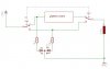
So I rig up a simple potential divider, and drop the voltage of the supply down a few volts, and the fan stops completly. Working my way up from this voltage, I increased it until the fan started spinning. It spun alot slower, and I then worked out what voltage this would be. Assuming that the supply was exactly 12v, I would have been giving the fan 11.97v

How come my fan almost stops when I drop the supply by only 0.03v???!!!??? I don't understand it.

Ok, so maybe my "voltage controlls speed" theory was wrong. What does control the speed of computer fans?

Thanks a lot

Tim
 
what resistor values did you use in your divider?

voltage does control speed, but keep in mind that some fans need there full voltage (in this case 12V) to start. Once it is running you can lower the voltage and speed should reduce too.
 
err the top resistor was 150R, the bottom two (in series) was 59K.

Do the calculation if you like, but however you do them, its very silly.
 
It doesn't work that way. your divider will indeed seperate the voltage a certain way when it is unloaded!. If you connect the fan then these values won't be the same anymore, because the fan itself has a certain impedance wich comes in parallel with one of the resistors...

what you need is a real voltage regulator (using LM317 for example). give the fan 12V at startup and then regulate it down to required speed...
 
your variable speed fan controller will work better with a PWM drive voltage. these circuits apply the full 12 volts in pulses spaced apart to vary the speed. this design will give the fan the voltage it needs to overcome the mechanical inertia required to start the fan and keep it turning, while the spaces allow the fan to coast down to a lower speed before the next pulse. The result is an average lower speed. think of it like "blipping" the throttle on an engine.

lowering the input voltage to a fixed level will work, but it has limitations depending on the fan motor.

search the net for " PWM computer fan controller" and you will find many circuits, along with several ideas here in this forum
 
the fan itself has a certain impedance wich comes in parallel with one of the resistors...
lol, I didn't think of that!!

what you need is a real voltage regulator
don't most regulators need a couple of volts headroom? In which case you'd never be able run it at full speed...?

zevon8, will look for some, sounds like it would work better than anything I came up with!!I always thought PWM controllers were just for AC motors though... What you said about the average speed makes sense, I just never realised that.

Cheers guys

Tim
 
yes, you will probabely lose a little when using a LM317, but is probabely the simplest way. PWM would be better indeed, but requires some more components...
 
i'm currently looking for some very low component count circuits, just because I have very little room to fit it in. don't suppose you have any circuits lying around?

Thanks

Tim
 
for PWM, a pic and a transistor would do, but you need some pic expierence...

if you search on google, i'm sure you'll find some 555 based pwm circuits as well

for the LM317 option i found this
**broken link removed**
 
agrreed Exo, variable regulator is the simple way.

my only problem with them is the generally limited range of speed control. sometimes if you set a fan to a low speed with one ( after turning it on ) the voltage is too low the next time you start your PC, and the fan does nothing. of course this can be avoided thru experimentation.

there are PWM controllers based on 555 timers driving output transistors that are around 15 parts, easy/cheap to build and set-up.

I did one a while back for a friend, the whole thing was about 2" square and the speed control pot mounted on a drive bay blank panel, circuit board "hanging" from the pot.

here's one similar to what I used:

**broken link removed**
 
thats the sort of thing I'm looking for

i think I will also 'hang' it off the pot, as it has to go on a blanking plate on a drive bay
 
instead of using a supply (12v or 5v) and connect the other side to ground, use 12v to 5v (giving u 7V). using these combinations u get a 3 speed fan(5v, 7v and 12v) w/o the need for parts (other than switch)
 
ok, i looked at the link you posted zevon8, i have a question.

if I had the pot full to one end, would the fan go at full speed?

having read some stuff about this PWM lark, I may acutally go with the variable regulator, simply because the tach won't output anything at all useful if i'm using PWM to vary the speed.

Well, actually, i'll go with the PWM for my 0.15A fan (which doesn't have a tach) and variable regulator method for my 0.6A fan (which does have a tach). Which brings me nicely onto my other question, how much heat sinkage would I need drawing 0.6A through a 1A regulator (I don't want to add extra heat to my computer case - that seems to defeat the point)

Cheers guys, you're a big help

Tim

P.S. i'm having trouble understanding the current handle-ing capabilities of transistors, using the tip120 as an example (https://www.electro-tech-online.com/custompdfs/2004/07/tip120.pdf), how much current/load could i put on it? Would it get hot?
 
it can handle 5A collector current.
how hot it will get depends on the current you draw from it...
The total heat produced in watts = current * Vce.
According to the datasheet Vce is about 2V
 
Cheers Exo, thats really helpful.

I've though about this a lot, and decided that the regulator is a better idea, but will not allow me to run it full speed. So I thought that maybe i could use a SPDT switch so I can switch between full speed and controlled speed. A la 'diag1.gif'

A couple of problems you might be able to help me with here - on the 'speed controlled supply for fan' connection, if I was in full speed mode, would current flowing back into the speed controll cause any problems? (bearing in mind that the supply for the speed controller would be cut off)

However, I then thought it would be cool to have an LED to tell me if the fan is running or not. Then I though it would be even cooler if the LED lit up a different colour depending if I was in in full speed or speed controlled mode. Hence, I created 'diag2.gif'

However, as well as with the existing problem detailed above, there is another one. When the fan is in speed controlled mode, current from the speed controller would flow back up the full speed connection for the fan, and travel to the LED. Thus when in speed controlled mode, the LED would light both colours, and is using PWM, would pulse into the other colour (this may look cool, but it would be realy annoying). This could be solved with a diode, but I can't afford the voltage drop. :(

Any suggestions/ideas will be much appreciated.

Thanks again

Tim
 

Attachments

  • diag1.gif
    diag1.gif
    3 KB · Views: 418
  • diag2.gif
    diag2.gif
    3.6 KB · Views: 423
just use a dual SPDT switch (2 switches in one case, mechanically connected together)
 

Attachments

  • sch1.jpg
    sch1.jpg
    19.9 KB · Views: 412
There are special purpose fan speed control ICs available. If you do a search for "Fan" on Digikey.com you should come up with some. They are basicly voltage to PWM converters. Some are designed to use a cheap diode as the temperature sensor.
 
cheers Exo, i though of using a double pole switch, but couldn't work out how to puy it together! Thanks for taking the time to draw the diag. it solved both problems!!

bmcculla, I'll look into it.

Cheers guys

Tim
 
You can make your own voltage regulator with an op-amp driving a MOSFET. Either N-channel or P-channel will work, you would just change the output direction. This solution has no minimum regulator voltage dropout.

If the input is known to be a regulated 12V, you don't need a zener diode to create a known voltage, a resistive divider will do. Compare against the output voltage, and include a cap to slow down the feedback response a lot to prevent oscillation.
 
Status
Not open for further replies.

Latest threads

New Articles From Microcontroller Tips

Back
Top