Continue to Site

Welcome to our site!

Electro Tech is an online community (with over 170,000 members) who enjoy talking about and building electronic circuits, projects and gadgets. To participate you need to register. Registration is free. Click here to register now.

  • Welcome to our site! Electro Tech is an online community (with over 170,000 members) who enjoy talking about and building electronic circuits, projects and gadgets. To participate you need to register. Registration is free. Click here to register now.

Bypass touch button on fan

D

Danster

Guest
Hi there,
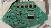
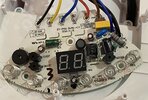
I have ask how can I bypass the touch button on fan Sencor SFE 2340WH, please? I want to of/off fan with smart momentary switch. Below is componets names, maybe with reading errors and photos of con board. Thank for all suggestions.

PS: The best solution will be if i will be able to bypass it by two wires (NO/COM). Like in this post.

Components:
TR1-TR5:
HSDQ / BT134-800 / A2040D
MCU1:SOC / SC93F8333M (datasheet link)
U1: PN6007 / M35A17
 

Attachments

  • back-side of pcb.jpg
    back-side of pcb.jpg
    654.3 KB · Views: 157
  • front-side of pcb.jpg
    front-side of pcb.jpg
    1.7 MB · Views: 158
Last edited by a moderator:
Solution
Yeah, I know but it can be plugged into outlet upside down, so L can be plugged into N…
That is the same for most circuits connected to the mains.

The fan circuit contains a low voltage supply, which runs the processor, labelled MCU1. That supply will most likely be 3.3 V or 5 V, so there is 3.3 V or 5 V between the +ve (Vdd) and -ve (Vss) of that supply. The voltage between the -ve of that supply and ground could be a wide range of voltages, and it may depend on which way round the plug is connected.

The voltage between the -ve of the supply and ground doesn't really matter because nothing is connected between those two points. The 3.3 V or 5 V is important because that processor runs from that supply.

I think that the relay...
I would probably bypass the entire circuit board.

The fan will most likely run when mains power is connected between "L" and one of "LOW", "MID" and "HI". If you pick a speed, and connect the remote switch in series, then the fan can be turned on and off remotely using the remote in its latching mode. The remote must be rated to the mains voltage and the current that the fan takes to work like that.

If you want to keep the control board, connect the remote to the ON/OFF connection with a capacitor in series, and the other side of the remote to ground. You should use a small, mains rated capacitor, maybe 100 pF. That should simulate someone pressing the button. The remote would be used in its momentary mode.
Thank you for your idea, but i want find way, how i can baypass only button, because that fan have remote control, and i want to use it as well.
 
Well the method with a capacitor and connecting to the button connection is likely to work. It might not, as it is not clear what the original circuit is actually measuring from the buttons.
Can you please draw me where i have to connect capacitor and momentary switch? And there is way to bypass it on MCU1 (microcontroller) componet?
 
1688301138545.png

This is what I am suggesting. You should keep the smart switch close to the fan, like a few cm away.

I don't know what you mean about bypassing it on the MCU. You could send a signal to the MCU, you can make the output device turn on without the MCU turning it on, or you can change the way that the MCU works by changing its programming or replacing it. Which one do you mean?

My suggestion is trying to fool the input into thinking that someone has touched the ON/OFF button. The ON/OFF button connects directly to the MCU via R34 which is 560 Ohms.

The MCU controls the five transistors TR1 to TR5 via five resistors, each of 270 Ohm. They are R6, R10, R11 and two that I can't read, but the resistors are all labelled "271". You might be able to turn the transistors on with some circuitry other than the MCU.
 
And capacitor in that circuit will be 100pF yeah? And where i can connect ground (i mean can i find it on pcb board?).

Yeah, I mean send signal to mcu like in this post (without any capacitor or anything else). Will by that possible?

PS: Sorry for my bad english.
 
The capacitor will be 100 pF. Ground should be the mains ground. It may not be on the board at all.

When those touch switches work normally, they are measuring the capacitance to ground through whoever touches them. That is what you are trying to simulate.
 
I think that the wire that connects to all five of the big transistors is the negative of the circuit, but I am not sure if connecting the ground of the relay to that point will work.

That whole circuit is not isolated from ground. You should consider any part of it to be as dangerous as the mains electrical supply.
 
Hi there,
I have ask how can I bypass the touch button on fan Sencor SFE 2340WH, please? I want to of/off fan with smart momentary switch. Below is componets names, maybe with reading errors and photos of con board. Thank for all suggestions.

PS: The best solution will be if i will be able to bypass it by two wires (NO/COM). Like in this post.

Components:
TR1-TR5:
HSDQ / BT134-800 / A2040D
MCU1:SOC / SC93F8333M (datasheet link)
U1: PN6007 / M35A17 countertop resurfacing dallas
How do eliminate the touch switch so the machine comes on when given power? R23 is the switch.
 
The capacitor will be 100 pF. Ground should be the mains ground. It may not be on the board at all.

When those touch switches work normally, they are measuring the capacitance to ground through whoever touches them. That is what you are trying to simulate.
That capacitor can have capacity more or less than 100pF or it have to be exact value 100pF? And for what voltage that capacitor should be?

According to datasheet for MCU ground should be at MCU1 at VSS pin, or am I wrong?
 
100 pF is my guess based on the capacitance of a person to ground. You should have a capacitor rated to mains voltage.

I tryied it. And it can be simulate with piece of wire without capacitor. The new problem is so it simulate touch everytime when you touch it with wire. So it somulate touch when it disconnected in momentary switch.
 
I tryied it. And it can be simulate with piece of wire without capacitor. The new problem is so it simulate touch everytime when you touch it with wire. So it somulate touch when it disconnected in momentary switch.
For that approach to work , you need to get the capacitance of the switch to a very low value. If they are any suppression devices on the switch circuit you will have to remove them.

As I mentioned in post #6, the switch needs to be close to the fan. That is to minimise capacitance to ground.

You could also try a capacitor smaller than 100 pF in series. The fan circuit detects a person through the plastic, so the maximum capacitance it will normally be connected to is very small.
But when you touch contact of touch button with simple 5 cm wire it also trigger touch button
 

Latest threads

New Articles From Microcontroller Tips

Back
Top