Continue to Site

Welcome to our site!

Electro Tech is an online community (with over 170,000 members) who enjoy talking about and building electronic circuits, projects and gadgets. To participate you need to register. Registration is free. Click here to register now.

  • Welcome to our site! Electro Tech is an online community (with over 170,000 members) who enjoy talking about and building electronic circuits, projects and gadgets. To participate you need to register. Registration is free. Click here to register now.

Bypass touch button on fan

D

Danster

Guest
Hi there,
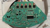
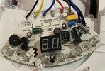
I have ask how can I bypass the touch button on fan Sencor SFE 2340WH, please? I want to of/off fan with smart momentary switch. Below is componets names, maybe with reading errors and photos of con board. Thank for all suggestions.

PS: The best solution will be if i will be able to bypass it by two wires (NO/COM). Like in this post.

Components:
TR1-TR5:
HSDQ / BT134-800 / A2040D
MCU1:SOC / SC93F8333M (datasheet link)
U1: PN6007 / M35A17
 

Attachments

  • back-side of pcb.jpg
    back-side of pcb.jpg
    654.3 KB · Views: 157
  • front-side of pcb.jpg
    front-side of pcb.jpg
    1.7 MB · Views: 158
Last edited by a moderator:
Solution
Yeah, I know but it can be plugged into outlet upside down, so L can be plugged into N…
That is the same for most circuits connected to the mains.

The fan circuit contains a low voltage supply, which runs the processor, labelled MCU1. That supply will most likely be 3.3 V or 5 V, so there is 3.3 V or 5 V between the +ve (Vdd) and -ve (Vss) of that supply. The voltage between the -ve of that supply and ground could be a wide range of voltages, and it may depend on which way round the plug is connected.

The voltage between the -ve of the supply and ground doesn't really matter because nothing is connected between those two points. The 3.3 V or 5 V is important because that processor runs from that supply.

I think that the relay...
As i said, like 5cm
If that 5cm wire isn’t connected to or close to anything, it will be quite difficult to create a switch circuit that doesn’t permanently trigger the circuit.

You could try connecting normally open relay contacts between the switch input and the circuit ground that connects to all the big transistors. Tell us if that triggers the circuit.
I am not sure where is the ground that connects to all big transistors, as the fan have two pin plug european (Live and Neutral) and it can be reversed when plug in to power socket. I am worried that I connect 230v to the touch button.
800px-Euro-Flachstecker_2.jpg
 
I meant the wider pcb track that is at the top of your photo. That track connects to each of the transistors TR1 ... TR5. It is the ground for the circuit, even if it isn't connected to mains earth.

(I now think that they may be triacs, not transistors)
Yeah, I know but it can be plugged into outlet upside down, so L can be plugged into N…
 
Yeah, I know but it can be plugged into outlet upside down, so L can be plugged into N…
That is the same for most circuits connected to the mains.

The fan circuit contains a low voltage supply, which runs the processor, labelled MCU1. That supply will most likely be 3.3 V or 5 V, so there is 3.3 V or 5 V between the +ve (Vdd) and -ve (Vss) of that supply. The voltage between the -ve of that supply and ground could be a wide range of voltages, and it may depend on which way round the plug is connected.

The voltage between the -ve of the supply and ground doesn't really matter because nothing is connected between those two points. The 3.3 V or 5 V is important because that processor runs from that supply.

I think that the relay has a better chance of working if connected to the -ve (Vss) instead of Vdd in your post #24. Also I suggest common connected to Vss and the touch pin connected to NC.
 
Solution
That is the same for most circuits connected to the mains.

The fan circuit contains a low voltage supply, which runs the processor, labelled MCU1. That supply will most likely be 3.3 V or 5 V, so there is 3.3 V or 5 V between the +ve (Vdd) and -ve (Vss) of that supply. The voltage between the -ve of that supply and ground could be a wide range of voltages, and it may depend on which way round the plug is connected.

The voltage between the -ve of the supply and ground doesn't really matter because nothing is connected between those two points. The 3.3 V or 5 V is important because that processor runs from that supply.

I think that the relay has a better chance of working if connected to the -ve (Vss) instead of Vdd in your post #24. Also I suggest common connected to Vss and the touch pin connected to NC.
Nice, thank you, it worked! VSS pin to COM on momentary switch and TOUCH BUTTON pin to NO on momentary switch.
pcb_with_switch.jpg
 
That is the same for most circuits connected to the mains.

The fan circuit contains a low voltage supply, which runs the processor, labelled MCU1. That supply will most likely be 3.3 V or 5 V, so there is 3.3 V or 5 V between the +ve (Vdd) and -ve (Vss) of that supply. The voltage between the -ve of that supply and ground could be a wide range of voltages, and it may depend on which way round the plug is connected.

The voltage between the -ve of the supply and ground doesn't really matter because nothing is connected between those two points. The 3.3 V or 5 V is important because that processor runs from that supply.

I think that the relay has a better chance of working if connected to the -ve (Vss) instead of Vdd in your post #24. Also I suggest common connected to Vss and the touch pin connected to NC.
It can be used without resistor when its working with wire? Like post #28?
 

Latest threads

New Articles From Microcontroller Tips

Back
Top