Continue to Site

Welcome to our site!

Electro Tech is an online community (with over 170,000 members) who enjoy talking about and building electronic circuits, projects and gadgets. To participate you need to register. Registration is free. Click here to register now.

  • Welcome to our site! Electro Tech is an online community (with over 170,000 members) who enjoy talking about and building electronic circuits, projects and gadgets. To participate you need to register. Registration is free. Click here to register now.

LTspice AC/DC convertor

Status
Not open for further replies.
Yes I did, tried the circuit with LT8312 from #17. It seems to work there.

1. Ok, I reduce the capacitor to 1uF
2. So what I understand, I need to have another LT8312 connected? I mean, one PFC controller to Q1 and an another PFC controller to Q2? You want "interleave". Or is it possible to have only one, and having interleave = .A.B.A.B.A?
3. I forgot to add K2 L3 L4 1 , my misstake.
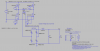
4. I added R3 because I want to make sure I have an input current of 16 A. D11, D12 is there because the circuit on configuration looks like that according to the scientist paper. But maybe they are not needed? See the attached files.

Thank you,
 

Attachments

  • AnAutomotiveOn-Board3.3kWBatteryChargerforPHEVApplication_ NEW.pdf
    1.7 MB · Views: 244
  • forum10.png
    forum10.png
    55.2 KB · Views: 280
Aha, I see.

Hmm, it is possible to change some of the voltage sources with AC phase (180 degree) to the LT8312?
Cause I do not think there is an interleaved PFC controller for LTspice. I guess there is one for Pspice tough.
 
Okay, I will try that. But first, I felt I needed to go back some steps. So I now I focusing on 1-phase PFC (so no interleaved). I think I succeeded to implement a LT1249, and it seems to work.
I will try with the LT8312 as well and see how it goes.

But for the DC/DC converter stage, do you how to increase the voltage to around 30o V at the output? I got only around 200 V.
I need a voltage range between 320-380 V in order to charger the battery in vehicle. I tried to change many parameters in the circuit, but it seems not to increase.

If you have time, you can please have a look on that. I am so thankful for your help.
 

Attachments

  • AC-DC with PFC_LT1249.asc
    4.8 KB · Views: 206
  • DC_DC Converter DEMO.asc
    4.2 KB · Views: 194
It is very common for people to think that if you put a voltage on the Gate of a MOSFET the transistor will turn on. The signal must be from Gate to Source. See the changes to M1 and M3 and how they connect to V1 and V3.
upload_2018-3-6_17-8-45.png

Next your transformer had problems. I changed to 1:1 transformer and increased the inductance.
Try this.
 

Attachments

  • DC_DC Converter DEMO_ron.asc
    4.1 KB · Views: 187
Ah, I see. But doesnt M2 and M4 also need to have the same connection as M1 and M3, regarding a signal from gate to source as well?
Okay, so the transformer should have 1:1 ratio. But I notice that, I could reach about 320 V output from the converter if the inductance been reduced, maybe that's what you meant.

Do you think the output voltage is DC enough in order to charge a battery? (I am however not sure about the battery model is correct, need to find one that is corresponding to a lithium battery for a PHEV).
 

Attachments

  • DC_DC Converter DEMO_ron.asc
    5.5 KB · Views: 181
  • forum11.png
    forum11.png
    40.5 KB · Views: 216
  • forum12.png
    forum12.png
    78.4 KB · Views: 210
Hmm, I don't understand why the circuits behave differently when I am just putting in the same file.
The AC/DC converter do not give the same output voltage, and likewise with the DC/DC converter.
Have I missed something?
Because, if these both converters operates properly, I was thinking to connect them together. But maybe that was too early I guess.
 

Attachments

  • TEST AC to DC.asc
    13.2 KB · Views: 195
Ah, I see. But doesnt M2 and M4 also need to have the same connection as M1 and M3, regarding a signal from gate to source as well?
You had the bottom two MOSFETs correct. (either way you drew them will work)

Your top two MOSFETs were wrong. Then the Gate goes to 10V the MOSFET turns on and pulls it Source up to about 5V and then stops. The output of the bridge is; pull down good but pull up to only 5 volts).

Okay, so the transformer should have 1:1 ratio. But I notice that, I could reach about 320 V output from the converter if the inductance been reduced, maybe that's what you meant.
Because you could only get 5V (in the old circuit) you changed the transformer to a very large turn ratio trying to amplify the 5V to get 200V.

Do you think the output voltage is DC enough in order to charge a battery?
"DC enough" I think some ripple on the output is OK. A car battery charger often does not have capacitors on the output. (very large ripple)

battery model
I have seen good batteries model. I often use a voltage source and a resistor (some times add a diode so it only charges).
Example: 12V battery like a car battery. I know at heavy charging current it will measure 14.5V. I often use a 12V voltage source and a 0.1 ohm resistor. At 0 to 12V the current is zero. At 10A charging current the voltage is 13. At 20A the voltage is 14V.
 
Okay, I see. Thank you for your great answers. I really appreciate it. I will try to fix a high voltage battery model that is corresponding to a PHEV.

Sorry, if I am being annoying, but the post in #28, why do you think the circuits do not match with each other?
Could you please maybe analyze what could be the problem?
 

Attachments

  • TEST AC to DC.asc
    13.1 KB · Views: 191
Last edited:
Hello again ronsimpson, I need some advice what to do now. I have tried to simulate the PFC interleaved, but it seems not to working.
I have decided to separate the AC/DC circuit and DC/DC circuit from each other, and simulate them one by one.

Do you think it is possible to use only voltage sources as pulses, instead to implement a IC circuit of the PFC (since it is complexed), to simulate an interleaved PFC? Is it possible? Do you have an idea how to do it? I would really thankful if you could help me once more.

I have attached my attempt to do it. However, I am trying to add EMI-filter after the input, is it consisting of 2 inductors, and 2 capacitors? I am not sure. Some sources says it is including more than that.
 

Attachments

  • ACDCPFC.asc
    3.8 KB · Views: 187
If you really have to do interleaved in SPICE, and there are no ICs in SPICE, then use a Linear.com part and:
1) connect MOSFET like normal.
2) IC output ---(5uS delay)---Gate of second MOSFET.
This is not perfect but almost does interleaved.

https://www.ti.com/product/ucc28070
 
Okay, I see. But what linear.com part do we talking about? Sorry, that I do not follow.

But do I really need to use ICs circuit necessarily, in order to simulate interleaved. It is not possible only to use voltage sources (since the current and voltage are already in phase with each other) connected to the MOSFETs?
 
I made my AC/DC converter stage only using voltage sources that are sending PWM (corresponding to PFC circuit as the voltage and current is in phase).
Do you think the current can be so low from the output from the converter? its only about 500 mA, and I know from design spec it can be maximum 12 A.
Is it reasonable with 500 mA?
 

Attachments

  • OBC_ACDC_16A_Filter.asc
    5 KB · Views: 232
  • forum.png
    forum.png
    46.6 KB · Views: 191
If you really have to do interleaved in SPICE, and there are no ICs in SPICE, then use a Linear.com part and:
1) connect MOSFET like normal.
2) IC output ---(5uS delay)---Gate of second MOSFET.
This is not perfect but almost does interleaved.

https://www.ti.com/product/ucc28070
Could you maybe show me how to use a Linear.com part? I am not sure what to use there?
I need to save some time, so I would be thankful if you could help me. If this is the best way to simulate interleaved, I am happy to have that.
 
Look at the datasheet for the LT1249. It includes a typical application circuit.
 
I have checked that model, it should look something like this I imagine.
But can you check for errors please? I do not think it works properly, the output looks strange.

And about the input current? Do you know other ways to change the current? Cause my task is to make sure to that I have
230 V (rms) with an input current of 4 A, 6 A and 8 A. I must try for all of these currents. Thank you.
 

Attachments

  • OFF_ACDC_4A.asc
    5 KB · Views: 185
Change the load on the output if you want to change the input current draw.
 
Your full wave bridge is not working. Remove the ground with the red X.
I do not know why R1.
upload_2018-4-3_7-28-12.png

It is not working right. It looks like the frequency response of the error amp is not right. C2,4, R3.
I don't have time to fix it today.
 
Status
Not open for further replies.

Latest threads

New Articles From Microcontroller Tips

Back
Top