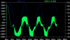
Continue to Site

Welcome to our site!

Electro Tech is an online community (with over 170,000 members) who enjoy talking about and building electronic circuits, projects and gadgets. To participate you need to register. Registration is free. Click here to register now.

  • Welcome to our site! Electro Tech is an online community (with over 170,000 members) who enjoy talking about and building electronic circuits, projects and gadgets. To participate you need to register. Registration is free. Click here to register now.

LTspice AC/DC convertor

Status
Not open for further replies.
325V @ 4A = 1300W.
1300W / 400V = 3.25 A.
400V / 3.25A = 123 Ω.

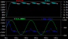
I see, but is it correct to use 325.27 (peak value)? Or i mean, is it correct to use 230 V (RMS) as well and do the same calculations?

Like this:
P=u*I = 230 *4 = 920 W
I = 920/400 =2.3 A
R=400/2.3 = 174 ohm

What value do you think that I should in the voltage source? 325.27 or 230 V ?
I think 325.27 should be okay, since I have put that value in the amplitude and that will give 230 V (RMS).
 
Last edited:
but is it correct to use 325.27 (peak value)? Or i mean, is it correct to use 230 V (RMS) as well and do the same calculations?
It depends if you're wanting to limit peak current or RMS current.
 
Then use 230V as the input voltage for the calculation.
 
Okay, 230 V (RMS) for the calculations, and 325.27 V (for the simulation, which gives 230 V (RMS). Just to make it clear what I am doing.

Do you how to change the switching frequency to 150 kHz? I think that I should you use this equation:

f_c = 1/(2 pi R C)

in order to calculate the values for C3 or R12 at the DCM.
What I understand from the LT8312 document, f_c needs to be lower than 12 Hz.

However, the time period of the output of one waveform period is always 10ms, so it means that I have 100 Hz as switching freq, even tough I tried to change the C3 and R12.

Could you please try to modify my file to see if you can obtain a higher frequency?
Thank you alec_t.
 

Attachments

  • OFF_ACDC_Boost_PFC.asc
    7.8 KB · Views: 193
Do you how to change the switching frequency to 150 kHz?
No. The LT8312 doesn't use a fixed oscillation frequency. It operates in the 'critical conduction mode' with a varying frequency which is load dependent and is a result of the power factor correction method that the IC uses.
 
Do you think its better to use the LT1249 instead? Its operating for 100 kHz fixed, but I can maybe assume its "close enough" to 150 kHz.
 
Why are you determined to use 150kHz?
 
Cause I need to reduce the component size in my design. The old design had 100 kHz, so that's why I need to increase the frequency.
 
but there is no standard demo for it
Yes there is.
1248Test.PNG
 
The resistor and capacitor on the Rset and Cset pins determine the oscillation frequency.
 
The resistor and capacitor on the Rset and Cset pins determine the oscillation frequency.
Yes I noticed that, thank you. I have selected 150 kHz. Alec_t, could you please check my LT1248 circuit? I think it works now.
 

Attachments

  • ACDC_PFC_LT1248.asc
    5.9 KB · Views: 184
  • inputVI.png
    inputVI.png
    55.9 KB · Views: 196
Last edited:
It works, but whether or not the component values are optimised for a 50Hz mains input and your chosen output voltage, I don't know.
 
If you really have to do interleaved in SPICE, and there are no ICs in SPICE, then use a Linear.com part and:
1) connect MOSFET like normal.
2) IC output ---(5uS delay)---Gate of second MOSFET.
This is not perfect but almost does interleaved.

I think I understand your suggestion, and yes, I agree with you that the interleaved do not need to be perfect.
I tried with LT1249, with 100 kHz internally in the IC-circuit, and I put a delay on the voltage source to connected to VCVS circuit.
The output looks okay, but I think the PFC doesn't work properly, since there is current spikes in the input. Maybe it is something with the switching parameters that needs to be adjusted?
 

Attachments

  • interleavedPFC.png
    interleavedPFC.png
    52.4 KB · Views: 211
  • OBC_INTERLEAVED_ACDC_LT1249.asc
    5.4 KB · Views: 177
The gate drive arrangement to Q2 is wrong. Q2 source is floating. Try using a BV device with the 'delay' function.
 
The gate drive arrangement to Q2 is wrong. Q2 source is floating. Try using a BV device with the 'delay' function.
You mean like this? or should I remove the whole VCVS circuit. What do you mean Q2 is floating? Is there something missing in the connections?
 

Attachments

  • OBC_INTERLEAVED_ACDC_LT1249.asc
    5.4 KB · Views: 174
Status
Not open for further replies.

Latest threads

New Articles From Microcontroller Tips

Back
Top