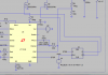
Ok, but although the PFC is now 'interleaved' (after a fashion), both FETS trigger on each GTDR pulse rather than on alternate pulses as etech mentions in post #84. I don't know enough about PFC to say if that's adequate, but perhaps it's ok with your supervisor?