Continue to Site

Welcome to our site!

Electro Tech is an online community (with over 170,000 members) who enjoy talking about and building electronic circuits, projects and gadgets. To participate you need to register. Registration is free. Click here to register now.

  • Welcome to our site! Electro Tech is an online community (with over 170,000 members) who enjoy talking about and building electronic circuits, projects and gadgets. To participate you need to register. Registration is free. Click here to register now.

LM3915 LED VU meter problem - pictures included

Status
Not open for further replies.
I checked, it looks fine. I also tested the other chip I have, but both of those are giving me same measurement values.

Hi,

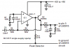
looking fine doesn't mean it is fine. To make sure pin2 is connected to ground connect the positive DMM probe to the positive rail of the supply.

Use the negative probe and measure directly at IC-pin2. The reading should be about +12V.

If there is no voltage to be measured the breadboard might be faulty not contacting the IC-pin.

Boncuk
 
The peak detector transistor is shown on the datasheet of the LM3915 with a peak input of 10V, not 1.25V as shown here. At lower levels it has a serious error.

I agree that the transistor is backwards. Looking at the flat on its case with its pins down it is EBC. European transistors like the BC547 are CBE.
 
Hi ! Did you manage to have your circuit working ?

If not, also make sure your LEDs are connected properly (the anode, longeur lead, goes to Vcc).

Also not shown in your picture is a wire linking your IPod's GND to the GND of your circuit. Do you have it ?
 
Hi all, thank you for the replies.

Here's the present setup, and I'm so confused now. I decided to change the place of pin #2 ground jumper which is seen as the long wire to the ground rail. There's no audio input to the board. I also fiddled with the position of the wires coming from the battery. This power-setup is supposed to be right as well, I mean the power and the ground just have to be connected somewhere, correct?

But now what happens when I plug the power is that every LED except no. 1 lights up immediately and stays on. And I have no idea what's happening.
 

Attachments

  • BB_copy_present..png
    BB_copy_present..png
    346.6 KB · Views: 633
"Fixed it", the transistor was the wrong way around (flat side up). Now it is flat down as in the pic, no LEDS light up.

UPDATE:

boncuk: I did what you suggested, and the pin # 2 gave a 12V reading.

technogilles: LEDs light up, so they should be ok. There's the mp3 sound ground too, it's just not drawn.

with the current setup, without audio signal in:

pin #1 = 0V

pin #2 = 0V

pin #3 = 12.3V

pin #4 = 11.8V

pin #5 = 12.0V

pin #6-8 = 11.8V

pin #9 = 12.3V
 
Last edited:
Audio leveling can be done without any problem by: ka 2285,
 

Attachments

  • 409-02086-0-KA2284[1].pdf
    76.8 KB · Views: 386
I changed the jumper wire for pin #2 to a longer one and I also changed the spot where it goes. Now pin #2 is 0V, but all the others are still 9.x

hi,
Ref the project board you are using, it looks quite new, is this the first project you have built on the board.?

If the voltmeter you have is able to measure resistance I would suggest you unplug the LM3915 from the board.
Use the ohm meter to measure the resistance from the 'hole' where a LM38915 pin would fit, to its expected destination on the board... I am beginning to suspect the board connections.

Whats your location.??
 
There is something wrong with the breadboard, definitely. It is a brand new and this is indeed my first ever thing with electronics in general :eek:

I did some testing with the pin #2 jumper wire going to the ground, and I noticed that there was a spot where the V of pin #2 changes from 0V to 12.3V. Exactly in the middle of the breadboard. If it was on the left side, 12V, and if on the right side, 0V. This isn't supposed to be the kind of board that splits from the middle, but could it be one nevertheless?

Here's a pic of the true situation, I didn't tell you this previously, because I honestly thought it would matter. You see, the breadboard is in reality twice the size, and I just showed half of it in the previous illustrations. The ground and the positive line from the 12V battery are on the far right end. I also tested this with a jumper wire in the middle, and when that was included, LEDS 2-8 lit up immediately when powering up.
 

Attachments

  • BB_problem..jpg
    BB_problem..jpg
    333.8 KB · Views: 701
There is something wrong with the breadboard, definitely. It is a brand new and this is indeed my first ever thing with electronics in general :eek:

I did some testing with the pin #2 jumper wire going to the ground, and I noticed that there was a spot where the V of pin #2 changes from 0V to 12.3V. Exactly in the middle of the breadboard. If it was on the left side, 12V, and if on the right side, 0V. This isn't supposed to be the kind of board that splits from the middle, but could it be one nevertheless?

Here's a pic of the true situation, I didn't tell you this previously, because I honestly thought it would matter. You see, the breadboard is in reality twice the size, and I just showed half of it in the previous illustrations. The ground and the positive line from the 12V battery are on the far right end. I also tested this with a jumper wire in the middle, and when that was included, LEDS 2-8 lit up immediately when powering up.

hi,
I have some boards just like that.!! its perfectly OK, just put a short jumper across the 4 gaps, 2 top and 2 bottom OK.

AAesp05..gif
 
Last edited:
Some success!

I did the small jumper connections for the + and - rails in the middle of the breadboard. Still, when I plug the power on, all the leds light up, but here's the new measurements from the chip:

pin #1 = 0.13V

pin #2 = 0V

pin #3 = 12.3V

pin #4 = 0V

pin #5 = 8.7V

pin #6 = 1.25V

pin #7 = 1.25V

pin #8 = 0V

pin #9 = 12.3V

These numbers make much more sense, don't they? I presume the reason why all the LEDs light up immediately is the voltage on pin #5?

EDIT: That damn transistor was upside down somehow AGAIN. I turned it the correct way, and now the voltage on pin #5 is 1.05V, which results in lall the LEDs except LED #10 not lit. But still, where is this 1.05V coming from...?

hi,
We are slowly getting there!
As a test, connect pin #5 to 0V, all the LED's should go off.

With that transistor circuit you will have a standing input of about 0.6V or so.

Lets get the basic circuit working first then we can sort out the transistor rectifier and if necessary add a simple one transistor amplifier.:)

Did you get that 5K pot yet.??

BTW: pin #1 , is the 1st LED in the line, pin 10 is the highest LED
 
Last edited:
Ok, I wired Pin #5 to 0V, and yes, all the LED's go off.

I had a problem with pin #1 LED not litting up previously, but that was because of burned LED, I changed the LED and now it's working and pin #1 has 12.3V like the other pins with voltage. I think LED #10, the highest one is not lit because pin #5 doesn't have 1.25V, just 1.05V.

I get the 5K pot tomorrow, the nearby electronics store closed early today. Should the pot be linear or logaritmic?

hi,
For a test, I would get a linear pot, it then can be used on other projects if required.

If you want to turn on all the LED's, connect pin #7 [1.25v] to pin #5.

The rectifier [transistor/diode] needs modifying, as it will give a poor/inaccurate response at low audio levels.
When you are satisfied with that the basic LM3915 is working OK, we can start looking at the audio input problems.

What colour are the LED's?
 
Last edited:
Ok, I'll get linear pot then.

LEDS 1-5 = Blue
LEDS 6-10 = White

I think that the LM3915 is working now, only thing that I don't understand why the pin #5 has 1.05V without any signal...
 
Last edited:
Ok, I'll get linear pot then.

LEDS 1-5 = Blue
LEDS 6-10 = White

I think that the LM3915 is working now, only thing that I don't understand why the pin #5 has 1.05V without any signal...

hi,
The voltage on pin 5 is due to current leakage thru the diode via that 10K to +12V.

What is your location.?
 
Last edited:
You have R5 connected to the wrong spot instead of it grounding the input pin 5.
If you add one resistor to make the reference voltage +10V like in the datasheet then the peak detector transistor will not turn on the first LED when there is no signal. With ther reference voltage at +10V then you will need a preamp opamp.

Maybe you should replace the peak detector transistor with a single-supply peak detector opamp circuit. I use it in my sound Level Indicator project.
Its output will be +1.25V peak like your LM3915 circuit. Reduce the value of R9 a little or increase the value of R8 for more gain but do nort give it too much gain. My circuit is attached and has a gain of 1.

Your 12.3V power supply is awfully high. It will cause heating in the IC when all the LEDs are turned on.
But the 1k resistor at pin 7 sets the current in each LED at only about 12mA so they will not be very bright and the heating in the IC will not be too bad (1.1W).
 

Attachments

  • peak detector..PNG
    peak detector..PNG
    16.2 KB · Views: 763
audioguru: I'll have to think about what you said a little more, lot to take in for an electronics newbie...

but regarding the LEDs, could I add another set of leds in series with the old ones to overcome this problem?

EDIT: How come the R5 is connected to the wrong spot?
 
Last edited:
hi agu,
I think you are misreading the image ref pin 5, it not very clear so I have highlighted the wires as I understand them to be.

Gaichuke,
I mean where do you live, country.:)

AAesp02.gif
 
Status
Not open for further replies.

Latest threads

New Articles From Microcontroller Tips

Back
Top