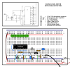
I got a loaner multimeter and I tried it to my circuit. I'm not quite sure how to measure with it, but here's what I did:
Red (+) pin from the multimeter to the pin in the chip
Black (-) pin from the multimeter to the circuit ground
12v works, I get about 12.3V through, and all the pins give 9.6V measurement. I think I'm doing something wrong.
I thank you for the patience to answer these...
")