Continue to Site

Welcome to our site!

Electro Tech is an online community (with over 170,000 members) who enjoy talking about and building electronic circuits, projects and gadgets. To participate you need to register. Registration is free. Click here to register now.

  • Welcome to our site! Electro Tech is an online community (with over 170,000 members) who enjoy talking about and building electronic circuits, projects and gadgets. To participate you need to register. Registration is free. Click here to register now.

LM3915 LED VU meter problem - pictures included

Status
Not open for further replies.
Yes, I figured it out almost immediately that there must be a short if component leads are in the same channel.

Now the LED pairs are working perfectly in series.
 
Last edited:
Yes, I figured it out almost immediately that there must be a short if component leads are in the same channel.

Now the LED pairs are working perfectly in series.

hi,
Do you have a 555 timer on your workbench.??

If yes, you could make a simple astable, running at about 1000Hz, use a 5k pot on the output pin #3 and drive your precision rectifier under test.

I know its a square wave output, but it will enable a quick test of your project...

BTW: often the 'K' is used in place of the decimal point, so 4.7K == 4K7
 
Audioguru,

I was looking that gain settings picture you showed me in post #108. I'm not seeing any difference between top right and low left pictures, yet they have different low cutoff frequencies. What am I missing here?
 
Sorry. I made a mistake in the lower left schematic.
For a cutoff frequency of 4.9Hz then R9 is 100k like the schematic above it.
For its gain to be 3 then R8 is 300k.
 

Attachments

  • peak detector gain.PNG
    peak detector gain.PNG
    48.6 KB · Views: 1,309
Last edited:
Sorry. I made a mistake in the lower left schematic.
For a cutoff frequency of 4.9Hz then R9 is 100k like the schematic above it.
For its gain to be 3 then R8 is 300k.

hi agu,
With the gain at 3, the problem I mentioned previously is worse.???

I know that you use LTS so I have attached the *.asc file, I would appreciate your comments on this 'effect'.
 

Attachments

  • PeakDect1.asc
    2.5 KB · Views: 202
  • PeakDect1.gif
    PeakDect1.gif
    28.4 KB · Views: 346
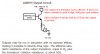
a question for LM3915, i already made a sensor of low-pass filter sound dBmeter using microphone with LM3915, and it seems the LED working, but the problem is, even the 10th LED not lighted, it already have a 4,5 volt DC current from the pin to the LED.. so i can't use it as a sensor if there's always 4,5 volt(that means always bit "1" and never "0", i want the sensor to be active high if the LM3915 reach max dB, by using the 10th LED current) if i'm gonna use the current to become an input for microcontroller.. is it true when the circuit is working, there's a voltage in the LEDs even it's not lighted by the LM3915 IC ?? oh, by the way, i'm using running dot mode.. a reply to this post is really appreciated
 
Last edited:
The datasheet shows that the outputs are the collector of an NPN transistor so they never go high unless you add a pullup resistor.
The outputs are constant current sinks that never go low unless you add a resistor in series with an LED.
Then the output will be a low when the LED turns on.

The datasheet shows that the first LED has a small current in it for cascading ICs when it is supposed to be turned off. It shows adding a 20k resistor across the LED so that it does not dimly glow.
 

Attachments

  • LM3915 outputs.PNG
    LM3915 outputs.PNG
    29.9 KB · Views: 507
Last edited:
The datasheet shows that the outputs are the collector of an NPN transistor so they never go high unless you add a pullup resistor.
The outputs are constant current sinks that never go low unless you add a resistor in series with an LED.
Then the output will be a low when the LED turns on.

The datasheet shows that the first LED has a small current in it for cascading ICs when it is supposed to be turned off. It shows adding a 20k resistor across the LED so that it does not dimly glow.

so, in order to have an "active low" output from the 10th pin(the 10th LED) when it is "lighted"... i put a 50 Ohm resistor would be enough ?
because of it's 'constant' current from the pin ?
 
The resistor in series with the LED is calculated with the forward voltage of the LED, its amount of current and the supply voltage.
If the supply is 9V, the LED is a 1.8V red one and the current in it is set to 20mA then a 50 ohm resistor will have a voltage drop of only 50 ohms x 20mA= 1V which is nowhere near enough. The output "low' will be +6.2V which is not low enough.
 
Status
Not open for further replies.

New Articles From Microcontroller Tips

Back
Top