Electro Tech is an online community (with over 170,000 members) who enjoy talking about and building electronic circuits, projects and gadgets. To participate you need to register. Registration is free. Click here to register now.
Welcome to our site! Electro Tech is an online community (with over 170,000 members) who enjoy talking about and building electronic circuits, projects and gadgets. To participate you need to register. Registration is free. Click here to register now.
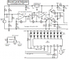
Here is the schematic of my Sound Level Indicator project. It has automatic gain control so it is very sensitive to low volume sounds but it cuts its sensitivity 20dB for louder sounds.
lol greetings all, of course the board noob has to bump an ages old thread
Looking into a sound reactive led project powering a couple of different colored led's to react to sound. My issue is this, I see a lot of projects geared toward vu meters where more lights react to higher db and what I am actually aiming for is to have the different led's react to different freq. for example a blue led reacts to bass and low sounds and a red reacts to the high sounds such as snare or voice etc. I wan't to work this into a speaker that a friend made (full fledge speaker he's very good) but he's paranoid that if i steal a few miliamps from him that the world will end. therfore i'd like to use a standalone power source such as a 9v and use a mic for the input of sound. someone quite bluntly answered with a simple "lm339a" lol but just looking at the dat sheet on this ic alone doesn't quite confirm with me what I need to do here. Perhaps audioguru's vu meter with a bit of a tweak here or there could be my answer? any help is appreciated this is my second project and my first being a simple seven segment display a 555 and some nicrome (first proven via bargraph led" some binary decimal decoders etc. and viola remote firework launcher had some help but that's what the web is for right? thanks in advance.
Making an LED light to the beat of music is easy.
Making a dB meter with 10 LEDs that indicate how many dBs is easy.
But making a lowpass active filter for the bass, a bandpass active filter for the mid frequencies and making a highpass active filter for the highs in addition to making 3 sepatate LED driver circuits is a lot of work.
bandpass filters, frequencies and tranistors oh my
well I tell you what if you could point me in the direction of some ic's that i should take a look at and maybe a hint of needed components I may be able to piece it together, I don't want to sound as if I'm asking you to do it for me however I'm at a loss as of where to begin here. Perhaps if i state my requirements first to see if it is even possible.
1. Needs to be robust and independant of itself. (ie: not attached to a sound card or speaker but battery powered and able to function as a standalone)
2. Does not neccesarily need to be extremely fine tuned. (ie: perhaps the circuit to react to a vague range of sound low/high or bass/treble as opposed to complex filters perhaps an ic exist's that with some tweaking of a pot and using two ic's wired to two sets of led's i could gain the effect as opposed to making it an accurate science)
3. Needs to take input from a mic onboard source (This is the most baffling part to me I don't know if a pbuzzer type device is around that would work from what i hear i can rip one out of an old radio or use an old desktop mic but my friend absolutely refuses to allow me to connect the circuit to any of the actual speaker components themselves lol hes screwy what can i say?)
Part of my problem is iv'e asked around a bit much and now im so confused with op-amp datasheets comparators voltage dividers spinning in my head. Thought maybe you would have a general idea of what components i would need then i could find those dat sheets with an idea and show it to my uncle joey (who is a bit more skilled than me in these things) and then we might get lucky with some more digging and get something thrown down in multisim and on a breadboard etc etc. sorry if im asking too much i know it's an idea and not a proof of concept but im at a loss here.
PS: that's a mighty clean schematic you drew there lol Mine only look good if multisim routes them for me lol.
Google has all the circuits for you:
1) Electret microphone preamp.
2) Active lowpass filter.
3) active bandpass filter.
4) Active highpass filter.
5) Datasheet for LM3915 bar-graph LED driver IC.
Then put them all together and you will have a 10 LED bargraph for bass sounds, another 10 LED bargraph for mid frequency sounds and a 10 LED bargraph for high frequency audio sounds.
The LEDs will quickly kill a little 9V battery.
We will help you if you have a problem with the circuits.
From some of the reading iv'e done thus far I've learned a few interesting things in regard's to low pass filters high pass etc, for example dsl filters are an example of low pass and high pass filters to seperate the dsl and pot signals on the same line, interesting stuff, Im vaguely familiar with the term as I dabble in synth music a little but I am not editing sine waves by hand by any means lol. Thanks for all of you help guru I'll read into it and most likely work on a few projects with filtering and attenuating frequencies and Move on from there.
Well I'm currently just experimenting with using an electret mic for input and studying the output of an lm741 opamp on the circuit to see if I can even get some useful output and so far no luck. I suspect the mic is horrid i stole it from the base of an old telephone lol. I am getting a new mic module and Ill see what happens from there. By any chance does anyone here know anything about the
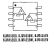
JRC45580? I can't seem to find a datasheet on it anywhere perhaps its under a different name but I can't find a lick of info on it. Was curious if it was a usable substitute for the lm741 was going to desolder it lol just get bored sometimes you know how it is. Well anyway thanks for all the help once i get a grip on the mic and the output from the 741 I can move on from there.
Lots of companies made or maybe they still make the old 4558 dual 741. Motorola had their MC4558 and National had their LM4558 and even New Japan Radio has their copy.
It is slightly better than a dual 741 because its full output bandwidth extends up to about 25kHz.
People say that this circuit works well. It stretches the pulse width to make the LED more visible.
Use it with the line level or headphone output of a CD or MP3 player. It might blow up with an output of a power amplifier unless an attenuator is added to the input.
The LED will light when the input has a peak voltage of 0.1V which is line level. It has a volume control to turn down the sensitivity.
The sensitivity is 10 times more when a 10uf capacitor is connected between pin 5 and pin 8.
People say that this circuit works well. It stretches the pulse width to make the LED more visible.
Use it with the line level or headphone output of a CD or MP3 player. It might blow up with an output of a power amplifier unless an attenuator is added to the input.
HI Audioguru - I know this thread is extremely old but I want to use this style of circuit in my truck. Can I use the RCA outputs on my car deck as the signal source with this setup? Also I am using 12v led's so which resistor would I subsitute?
The LM386 amplifier IC in my simple circuit is made to be powered from a 9V battery, not the 14.4V in a truck. It would need a voltage regulator circuit.
im going to be testing out haveing LEDS pulse with music.
But what about doing it with my car?
say about 16-20 leds in total. and making sure i dont blow out my leds.
how can i branch off from your circuit?
im going to be testing out haveing LEDS pulse with music.
But what about doing it with my car?
say about 16-20 leds in total. and making sure i dont blow out my leds.
how can i branch off from your circuit?
Somebody needs to design a current booster for the circuit to drive 16-20 LEDs.
LEDs burn out only when they do not have their current limited properly.
the Vin is the headphone positive and the circle under that is the headphone negative, correct?
but how come the 10k pot is connecting both and whats that black arrow right next to it?
got really confused haha
also why is the 470uF capacitor bridging the battery?
as i build this circuit i get more confused, how come the negative of the 9v battery connects to the LED then through the capacitor and resistor and back to the other end of the LED?
Thanks
The 10k resistor with arrow is how a volume control pot is drawn. The resistance track is connected between the input and ground to make an adjustable voltage divider for the signal. The arrow is the slider. Ground is 0V.
it keeps the voltage from the little 9V battery from jumping up and down when the LEDs light.
as i build this circuit i get more confused, how come the negative of the 9v battery connects to the LED then through the capacitor and resistor and back to the other end of the LED?
Simply connect everything together that are shown connected together on the schematic.
The negative of the battery connects to the headphones negative wire, the low end of the pot, the 1k resistor, the 10 ohm resistor, the negative wire of the 470uF capacitor, the cathode of the LED and the negative wire of the 220uf capacitor.
It might be confusing because the layout is for stripboard.
This site uses cookies to help personalise content, tailor your experience and to keep you logged in if you register.
By continuing to use this site, you are consenting to our use of cookies.