Electro Tech is an online community (with over 170,000 members) who enjoy talking about and building electronic circuits, projects and gadgets. To participate you need to register. Registration is free. Click here to register now.
Welcome to our site! Electro Tech is an online community (with over 170,000 members) who enjoy talking about and building electronic circuits, projects and gadgets. To participate you need to register. Registration is free. Click here to register now.
(Priliminary step__ My DMM has been cross checked with another by measuring my PC's +5V. Both meters were reading 5.12V)
1. Oh God - I interchanged 2 transistors (Q1 and Q4)by mistake. Today I have restored them.
2.the resistor R17 has been increased to 680 ohms due to very high brightness and consumption too.
3. The consumption at 5V external feeding was measured at 130mA.
After removing the 18F2550 it has come to 65mA. Now with 680 ohms, and transistors normalled , the current with f2550 in socket is 70mA with 5V supply.
4. the USB is still at 4.71V.
5. a) The trouble shooting procedure, the Vdd is indicated as if 4.5V. I don't Know where this measurement was taken. I presume it as measured at pin3 (TG_T) of 18f2550.
5. b) the Vpp is indicated as if, it is 11.9V. But actual measurement at collector of Q4 is only 10.99.V
6. The specific test of red color LED blinking, when powered while reset key pressed , is OK.
Now I am sure until I manage this voltage to 12.5V , perhaps I can't use it.
I propose to tamper the feed back ratio by reducing the R6 to get the required Voltage. I have used a 1% Tol resistor of 2K7 here.
Please offer your valuable comments and help me .
Meantime I am also trying to see how to improve the USB voltage of my PC. here I wan to attach a link to an Intel document PDF. If you google for this link you will land in usb.org link with a pdf suggested. perhaps it may be of help to us.
"Power Delivery Design Issues for Hi-Speed USB on Motherboards"
In my case the PC USB socket, the series resistor on 5V supply line is marked x15 ( I presume it to be 0.15 ohm. I would try to manipulate this to .075 by paralleling another. It might take time.
The 2N7000 and BS170 will both work, just depends on what part of the world you're in one will be more available than the other.
Preprogrammed 18F2550 comes with the kit, the firmware will update itself if it's older when you use MPLAB or PICKit2 software. You can even downgrade to 1.x if need be so you can recalibrate PIC12F chips (feature was removed in 2.x PICkit2 software)
DIY builders that have to supply their own 18F2550 will have to have access to a PIC programmer, sort of chicken before the egg problem.
Here's a useful tip for the MOSFETs (as they can be tricky to figure out DS)
* Use a multimeter to find the internal diode across D & S the Gate will be in the center.
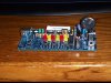
I finally got my junebug working!!! (big thanks to 3v0, Bill for the board, looks awesome)
Heres a pic:
It is pretty "special", as in ride the short bus special. Reistors and caps too big, crystal too big, no DIP Switch but shorting blocks, Massive Toroid, Messed up Ferrite bead (found off old monitor board, it is all twisted up) and tiny switches. But hey at least it can recognize chips and work!
I finally got my junebug working!!! (big thanks to 3v0, Bill for the board, looks awesome)
Heres a pic:
It is pretty "special", as in ride the short bus special. Reistors and caps too big, crystal too big, no DIP Switch but shorting blocks, Massive Toroid, Messed up
While we were working on it Krumlink asked what the bootloader button was for. I told him that he would have to re-flash the chip if he hit it. Not exactly right but close enough, I did not want to get into bootloaders at the point. He promptly posted the danger sign on the unit.
You mean the blinky program at the back of the Junebug manual?
Yes the instructions on the poster mostly apply, the poster is for version 7.x where 8.x has a release (normal) and debug selector on the toolbar but is otherwise similar to 7.
Just finished assembling my Junebug today, and I don't think its working quite right. I followed the directions to a T, and everything is identical to the picture. When I hook up to the USB cable, the green and yellow leds come on and the 3rd larger led comes on and goes off. I don't know where to start?
Just finished assembling my Junebug today, and I don't think its working quite right. I followed the directions to a T, and everything is identical to the picture. When I hook up to the USB cable, the green and yellow leds come on and the 3rd larger led comes on and goes off. I don't know where to start?
That sounds normal. LED 3 will come on when the 18F1320 is blank. The green & yellow are normal and the red may flash. Run the PICkit2 standalone software availabe in the PICkit 2 section of Microchips site.
3.8V seems too low though. Is that measured with a multimeter?
Yes, the voltage was measured with an old Fluke Multimeter. The only things I questioned during assembly was L1. All that was left that could go there was what looked like a larger resistor (1/2 watt?) than the rest. I think the colors were wrong for R6 also, but when I measured resistance of the one I installed in R6 it matched what the directions called for. Could either of these cause the low voltage?
This site uses cookies to help personalise content, tailor your experience and to keep you logged in if you register.
By continuing to use this site, you are consenting to our use of cookies.

")

