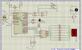
Hello! im doing a simulation mini project (temperature controlled fan) using PIC16F877A on Proteus and MPLAB IDE V8 for coding. i need help with my assembly code. i think there is something wrong with the temperature code section/AD conversion? Below is the details of the project:
Temperature controlled fan operations:
- LM35 as input for sensing temperature
- If start button pressed momentarily, system operation starts.
- if stop button pressed momentarily, all operation stop.
- 0-39°C (low temp) fan motor off, LED off, buzzer off and 7 segment display '0' indicate low temp.
- 40°C above (high temp) fan motor on, LED on, buzzer on and 7 segment display '1' indicate high temp.
Code:
;EQUATES SECTION

TMR0        EQU    1        ; TMR0 register
STATUS        EQU    3        ; STATUS register
PORTA        EQU    5        ; PORTA register
PORTB        EQU    6        ; PORTB register
PORTC        EQU    7
PORTD        EQU    8
PORTE        EQU    9
TRISA        EQU    85H        ; TRISA register address
TRISB        EQU    86H        ; TRISB register address
TRISC        EQU    87H
TRISD        EQU    88H
TRISE        EQU    89H
OPTION_R    EQU    81H        ; OPTION Register address
INTCON        EQU    0BH        ;Interrupt Control Register
GIE            EQU    7        ;Global Interrupt bit
INTE        EQU    4        ;B0 Interrupt Enable bit
INTF        EQU    1        ;B0 Interrupt Flag
ADCON0        EQU    1FH    ; A/D Configuration register 0
ADCON1        EQU    9FH    ; A/D Configuration register 1
ADRES        EQU    1EH    ; A/D Result register
CHS0        EQU    3        ; Channel select bit
GODONE        EQU    2        ; A/D Conversion Status bit
CARRY        EQU    0        ; Carry bit
ZEROBIT        EQU    2        ; Zero bit
COUNT        EQU    20H    ; COUNT register address
COUNTA        EQU    21H    ; COUNTA register address
TMR0_T        EQU    22H    ; Temporary register for TMR0
W_TEMP        EQU    23H    ; Temporary W register
STATUS_T    EQU    24H    ; Temporary STATUS register
PORTB_T        EQU    25H    ; Temporary PORTB register

;*****************************************************************************

    LIST    P=16F877A    ; Using 16F877 microcontroller
    ORG    0            ; Start address in memory
    GOTO    START

;*****************************************************************************

;CONFIGURATION BITS SECTION

    __CONFIG    H'3FF2'    ; HS oscillator, WDT off, PUT on, Code Protection disabled

;*****************************************************************************

;SUBROUTINE SECTION

; 10ms delay subroutine
DELAY    CLRF    TMR0            ; Clear TMR0
LOOPA    MOVF    TMR0, W            ; Move TMR0 to W
        SUBLW    .195            ; Subtract 195 from W
        BTFSS    STATUS, ZEROBIT    ; Check if result is zero
        GOTO    LOOPA            ; If not zero, repeat loop
        RETLW    0                ; If zero, return

;0.5sec delay
DELAYP5    MOVLW    .50                    ;W = 50
        MOVWF    COUNTA                ;W put inside file COUNTA
LOOPC    CALL    DELAY                ;goto delay
        DECFSZ    COUNTA                ;COUNTA - 1 = COUNTA
        GOTO    LOOPC                ;goto LOOPC
        RETLW    0                    ;COUNTA is 0, return

;1sec delay
DELAY1    MOVLW    .100                ;W = 100
        MOVWF    COUNT                ;W put inside file COUNT
LOOPB    CALL    DELAY                ;goto delay
        DECFSZ    COUNT                ;COUNT - 1 = COUNT
        GOTO    LOOPB                ;goto LOOPB
        RETLW    0                    ;COUNT is 0, return

COND1    BCF        PORTB, 5
        MOVLW   B'00000000'       ;set RA1 and RA2 high to turn on CP1 and CP2 LEDs
        MOVWF   PORTC              ;CP1 and CP2 LEDs turned on
         MOVLW   .0               ;load literal '0' to W register
        MOVWF   PORTD            ;Display '0' on 7-segment display for all parks full
        RETLW    0

COND2    BSF        PORTB, 5
        MOVLW   B'00001001'       ;set RA1 and RA2 high to turn on CP1 and CP2 LEDs
        MOVWF   PORTC              ;CP1 and CP2 LEDs turned on
        MOVLW   .1               ;load literal '0' to W register
        MOVWF   PORTD            ;Display '0' on 7-segment display for all parks full
        RETLW    0

;*****************************************************************************

;CONFIGURATION SECTION

START    BSF        STATUS, 5            ; Set bank to access TRISA and TRISB

    ; Configure PORTA and PORTB
    MOVLW    B'11111111'            ; PORTA as input
    MOVWF    TRISA

    MOVLW    B'00000000'
    MOVWF    ADCON1        ;all PORTA are analogue

    MOVLW    B'00000011'            ; PORTB as output
    MOVWF    TRISB

    MOVLW    B'00000000'
    MOVWF    TRISC

    MOVLW    B'00000000'
    MOVWF    TRISD

    MOVLW    B'00000000'
    MOVWF    TRISE

    ; Configure A/D Converter
    ;MOVLW    B'00000001'            ; PORTB,0 as input for A/D Converter
    ;MOVWF    TRISB
    ;MOVLW    B'00000000'            ; Set A/D Control Register 1 for analog input
    ;MOVWF    ADCON1

    ; Set up Timer0 for delay
    MOVLW    B'00000111'            ; Prescaler is /256
    MOVWF    OPTION_R

    BCF        STATUS, 5            ; Return bank to 0
    CLRF    PORTA                    ; Clear PORTA
    CLRF    PORTB                    ; Clear PORTB
    CLRF    PORTC
    CLRF    PORTD
    CLRF    PORTE
    CLRF    COUNT
    CLRF    COUNTA

    ; Turn on A/D Converter and enable interrupts
    BSF        ADCON0, 0            ; Turn ON A/D

;*****************************************************************************

;PROGRAM STARTS NOW

;SWITCH 1
MAIN    BTFSS   PORTB, 0          ;check if SW1 to start the operation is pressed (active low)
        GOTO    BEGIN            ;if pressed, go to begin
        GOTO    MAIN            ;if not pressed, wait for SW1 to be pressed

;SWITCH 2
BEGIN    BTFSS   PORTB, 1          ;check if SW2 to stop the operation is pressed (active low)
        GOTO    STOP            ;if pressed, go to stop

TEMP    BSF        ADCON0, CHS0        ;C to select A0
        BSF        ADCON0, GODONE    ;Measures temperature from AO, Set GO/DONE

WAIT    BTFSC    ADCON0, GODONE    ;Wait until GO/DONE is clear
        GOTO    WAIT            ;temperature loop in A/D reg. ADRES

        MOVF    ADRES, W            ;Move ADRES file content to W
        SUBLW    .82
        BTFSC    STATUS, CARRY
        GOTO    LOWTEMP
        GOTO    HITEMP        ; Otherwise, go to TEMP_ABOVE subroutine


LOWTEMP    CALL    COND1
        GOTO    BEGIN

HITEMP    CALL    COND2
        GOTO    BEGIN

;SWITCH 2 STOP OPERATION
STOP    BCF     PORTB, 5         ;set RA1 low to turn off CP1 LED
        MOVLW   B'00000000'       ;set RA1 and RA2 high to turn on CP1 and CP2 LEDs
        MOVWF   PORTC              ;CP1 and CP2 LEDs turned on
        MOVLW   .0               ;load literal '0' to W register
        MOVWF   PORTD            ;Display '0' on 7-segment display for stop operation
        GOTO    MAIN             ;restart operation

        END
Attachments
Last edited:

