Hi Adrian!
I have some more questions. Some of these questions aren't about the actual circuit, but they may help us help you better if the answers mean that we can look at other possible solutions.
Is this actually for a large-scale installation in a real hotel? If so, how many rooms must be serviced, and what is the expected range?
Actually, it is only for prototype purpose. But in my opinion, it should be as small as possible.I don't know how many room is going to be serviced since i was ordered to design such a circuit. What do you mean about the range? The room size or the remote device size?
Is using the remote controls your idea, or the hotel manager/owner's? I ask only because it sounds like they already have something central installed.
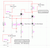
It is not my idea. Actually, this kind of function should not be wireless due to ot reliable. I think they should have missed to install such kind of service.
Do you know for sure that you can get enough remote controls with unique codes/addresses/frequencies/whatever to handle all the rooms?
This is a really good question and one of my problem too. But i think they can find different frequency remote controls. The range of the remote control should not too large but sufficient to cover a standard size room so the can use the same frequency remote controls in another room far apart.
Why do you want to do this with relays and capacitors only? If semiconductors and ICs were allowed it could possibly be made smaller and cheaper.
Not only relays capacitors can be used, any components can archieve this functions are also acceptable.
What is your expected budget for each unit? What about the budget for the whole system?
Budget is not a problem now but cheaper should be better
What is your deadline?
As soon as possible. But i don't want to bother all of you frequently... Anyway, It is my pleasure to have your help when you have free time")
What electronics experience do you have? Do you have the ability to load HEX code onto a microcontroller such as an 8051 or a PIC or something?
I haven't learn about how to use a microcontroller.
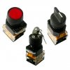
Would it be possible to use a rotary switch instead of a toggle?
er....If rotary switch is much more easy to build such device and user familiar. It should be acceptable.
I am sure I've forgotten some questions but if you can answer the above it might help us to help you.
Torben

") Oops...there I started thinking again.
Oops...there I started thinking again.