Continue to Site

Welcome to our site!

Electro Tech is an online community (with over 170,000 members) who enjoy talking about and building electronic circuits, projects and gadgets. To participate you need to register. Registration is free. Click here to register now.

  • Welcome to our site! Electro Tech is an online community (with over 170,000 members) who enjoy talking about and building electronic circuits, projects and gadgets. To participate you need to register. Registration is free. Click here to register now.

switch circuit

Torq

New Member
I'm new so my terminology will be off.
I have a working 12v vehicle CB that I would like to make a modification to.
I'd like for it to scan through the 40 channels on it's own.
With no modifications, I press/release the channel-up button, to go one channel up.
With no modifications, I press/hold the channel-up button it will RAPIDLY go through the channels.

My thought is to have a circuit to close the two pins on the channel up button, maybe once a second. Allowing time to hear activity on the channel.
one pin is 1v, the other is 10v-10.5v (varies each time powered up).
I tried an RC circuit but I'm doing something wrong.
It either goes one channel up just once, or it RAPIDLY goes through the channels.
T = 1 s = 1kΩ x 1 uF
 
I made the changes, but I'm not seeing the function I'm looking for.
I think the RC circuit is not enough, and maybe I need an oscillator?
I get one channel change with the RC each time I connect it, instead of multiple channel changes.
I will start looking at oscillator circuits.
 
The easiest way is to use a 555 timer IC in monostable or astable mode. Alternatively, if you need flexibility, you could use a small microcontroller (like an Arduino Nano).
 
Please post a schematic of your circuit. It doesn't have to be fancy, but it must show all signal and power connections. Be sure to include a unique reference designator for each component, connector, etc.

ak
 
I tried this circuit, but still have the same results of it speeding though the channels. I may have something wired wrong.
I'm assuming the 9k1Ω is a typo for 9kΩ.
I'm going to try simulating in LTspice to verify results before building.
https://www.analog.com/en/resources/design-tools-and-calculators/ltspice-simulator.html
If there is another simulator to try, please let me know.


1731858069645.png

 
R1 is 9k, try changing C to 2.2uf so timeout is ~22ms
VCC should be 12v.

If that doesn't work, you might have to drive an analog switch, or a small relay, with the 555 timer.
 
Last edited:
The circuit you show above is intended to provide a single long pulse each time the button is pressed; the values are daft though, it suits far longer delays than the button press time.


Try this version from the same site, and connect the button in series with the connection between VCC and Ra

If Ra is relatively small, eg. 1K, and Rb quite large, eg. 47k, the output will have almost symmetrical high & low times.

Try 47k and 10uF as a starting value? Or 100K if that is too fast.

tim68.gif


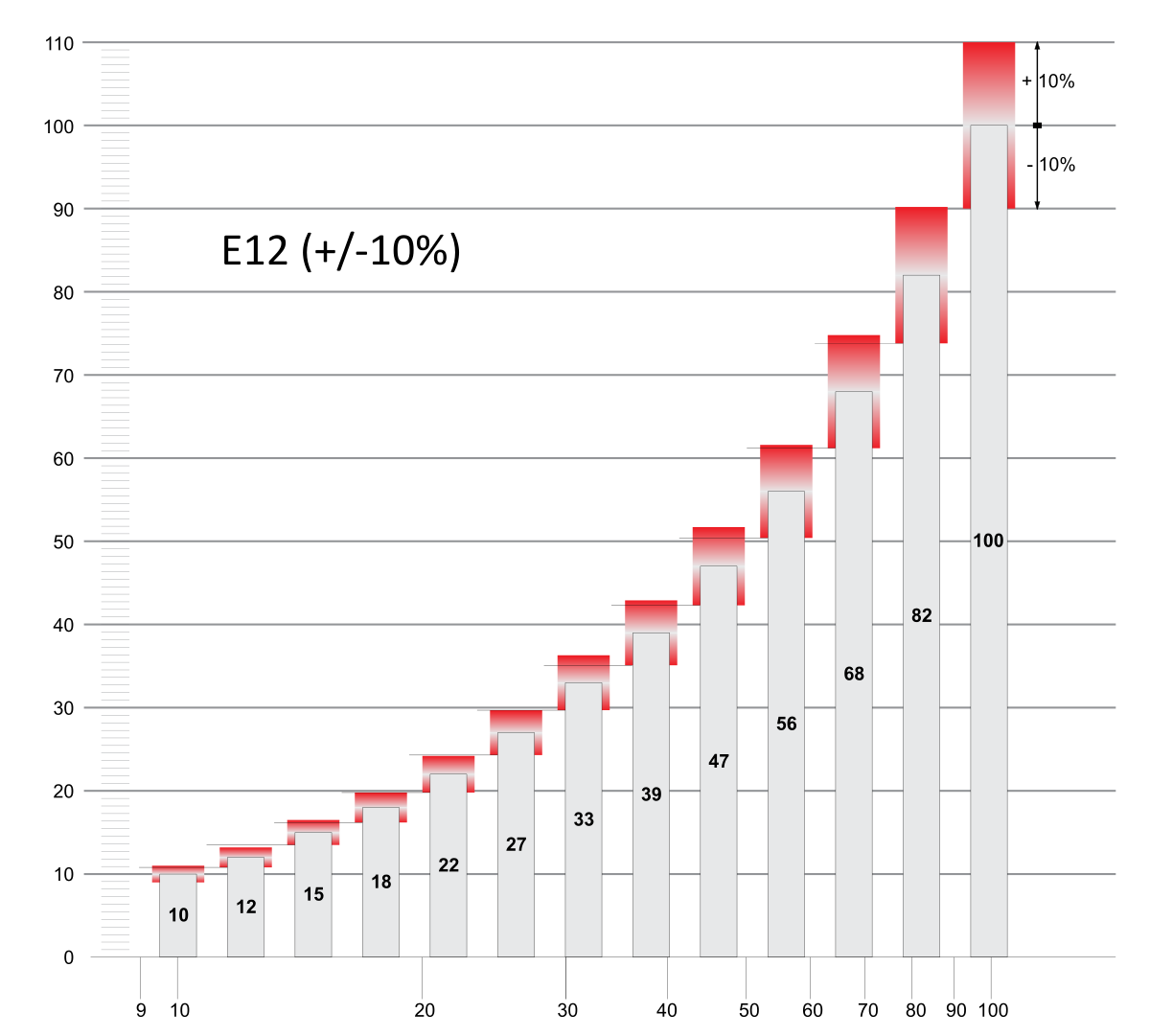
ps. 9k1 is a standard resistor value, in the "E24" series; 24 value increments per decade.
 
Here, turn on S1 to start your pulse train at 1Hz (approx) and press S2 to get Hz or more (depending on capacitor C1 size. R3 can be replaced by a wire (0 ohm) connection (my iPad simulator doesn't like capacitors in parallel).. Note, S2 is normally closed.
IMG_5799.jpeg
 
With no modifications, I press/release the channel-up button, to go one channel up.
With no modifications, I press/hold the channel-up button it will RAPIDLY go through the channels.
Below is the LTspice sim of ZZO's basic circuit without the added timing capacitor:
I added a pull-down resistor to the RST (/R) input, which is required for proper reset operation, since a RST open is equal to RST high.

1732126206657.png
 
Last edited:
Below is the LTspice sim of ZZO's basic circuit without the added timing capacitor:
I added a pull-down resistor to the RST (/R) input, which is required for proper reset operation, since a RST open is equal to RST high.

View attachment 147796
R4 was the reset pull-down in my circuit. How do you stop the scan to listen to a channel once interesting content is found?
 
R4 was the reset pull-down in my circuit.
It appears to be connected to +12V.
And the pull-down can be no larger than 1kΩ to insure Reset (look at the reset voltage and current specs).
How do you stop the scan to listen to a channel once interesting content is found?
Release the button on my circuit.
 
It appears to be connected to +12V.
And the pull-down can be no larger than 1kΩ to insure Reset (look at the reset voltage and current specs).

Release the button on my circuit.
Oops, you're right
 

New Articles From Microcontroller Tips

Back
Top