Torben
Well-Known Member
Hi Mike!
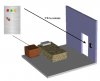
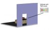
Yeah, I got that there would be one remote in each room. What I'm trying to determine is whether it's expected to reach only from a portable unit the customer can activate (say, from the bed or something) to light up the LEDs on a door unit, or whether the idea is that there will be some central control room which must receive signals from all the rooms.
If it's the first option, then Adrian's diagram might work, since no remote needs to be able to send a signal further than that room's door. If it's the second option, then I agree with you, and some other communication method should be looked at. I was thinking about Wifi or Zigbee modules, perhaps.
A wired approach would be easiest, I agree. But if the hotel owner doesn't want to lay wire for it, the only ways I can see to do that would be to piggyback on the phone or AC lines. Those ideas open their own cans of worms.")
Torben
Going by Adrians previous image. It would appear that there is a seperate remote for each room, ie. room 1 has freq 1, room 2 uses freq 2 etc. The drawing provided by Adrian would also imply a multi channel RX which I questioned. Adrian also assumed he could use redundant remote frequencies which would not interfere based on distance from TX room 1 with TX room 4, which would force multi RX units to maintain full floor coverage.
Yeah, I got that there would be one remote in each room. What I'm trying to determine is whether it's expected to reach only from a portable unit the customer can activate (say, from the bed or something) to light up the LEDs on a door unit, or whether the idea is that there will be some central control room which must receive signals from all the rooms.
If it's the first option, then Adrian's diagram might work, since no remote needs to be able to send a signal further than that room's door. If it's the second option, then I agree with you, and some other communication method should be looked at. I was thinking about Wifi or Zigbee modules, perhaps.
IMHO this plan is not to workable as is.
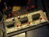
Perhaps the wireless idea be thrown out in lieu of a wired approach like a multi addressable 2 wire bus where the wires are ran under carpet or something.
I dunno...
A wired approach would be easiest, I agree. But if the hotel owner doesn't want to lay wire for it, the only ways I can see to do that would be to piggyback on the phone or AC lines. Those ideas open their own cans of worms.
Torben