Continue to Site

Welcome to our site!

Electro Tech is an online community (with over 170,000 members) who enjoy talking about and building electronic circuits, projects and gadgets. To participate you need to register. Registration is free. Click here to register now.

  • Welcome to our site! Electro Tech is an online community (with over 170,000 members) who enjoy talking about and building electronic circuits, projects and gadgets. To participate you need to register. Registration is free. Click here to register now.

Input 24Vac OutPut 40Vdc /1A circuits -issues

Status
Not open for further replies.

selva prabhu

New Member
Dear sir/ madam ,
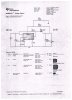
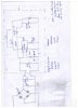
we use input voltage around 24 Vac and convert into dc by Full wave bridge (IN4007 )diodes with capacitors 2200uF/50v . so the output voltage is around 33vdc. we give this 33vdc to this circuit ,but in no load condition we get voltage but when we on with load condition the input current raise to 2-3A , i want to know how to reduce this input current .The Load we use is COB LED (FLOOD LIGHT) 36Vdc/1A. The Following component are used in this circuit .how solve this issue , we want to reduce the input current

Original Substitute

220nf /4V220nf/305V

33uF/63V22uF/200V

82uF/250V100uF/100V

DFLS1100-7ss210

330uH330uH

2.94K2.2K+1.2K(.25W)

1.5k2.2K .25W

71.5k82k .25W
 

Attachments

  • ti1.jpeg
    ti1.jpeg
    571.2 KB · Views: 316
input is 24vac and output is 33vdc.
Next is LED load.
Where is the attached circuit from Texas Instruments? Are you using it now or do you want to use it?

I think you say the 24Vac is 2 to 3A while the 33Vdc is 1A. How are you measuring the current?
"COB LED (FLOOD LIGHT) 36Vdc/1A" I need data on this light!

Problem 1) the 1N4007 diodes are 1A and you have a 1A load. You should be using 3A diodes.
Problem 2) I need to understand why 3A input and 1A output. something is not right
 
i have attached the circuit design for your reference ,yes TI only LM2588 IC

the input of this circuit requires 12-33vdc so we convert 24vac to dc by bridge gives as input . In no load condition we get output 37VDC , but while connect load ,we used check in power analyzer (PM100) . which we increases voltage by 5 itself using auto transformer , the circuits gets on .
The Load we use is CREE LED spec 38V/1.1A max
 
Last edited:
Thank you for the details of the LM2588. That informaton is good.

I think you have 24Vac.
Bridge rectifier and filter caps
33V DC
LM2588
37Vdc
LED 1.1A 38V

The input current you measure; Is it average (RMS) or peak?
This picture (left bottom) is a picture of input current. The peak is much higher than the average. That is the way it works. 1A average and 3-5A peak is typical.
Is this your problem?

upload_2014-8-2_6-47-26.png

ALSO

Never drive LEDs with voltage. They are current devices. You should drive the LED with a 1.1A (or less). You need a constant current PWM.
If you put 38V on a LED it might draw much less or much more current than you think. What is you LED current now?
 
The lm2576 can be used as a current source, I havent checked but theres a good chance with a few minor changes to the schem that the '2588 can be used as a current source too.
 
I rechecked the spec we use Cree Led for 40W we need driver 40V/1A ,for 20W we use 40v/500mA . so the voltage is constant we vary only current . we tried this ic also LM2585 but same issue only we are getting for the we use led with the spec 0.06W(3v/35 mA) per led .we use 15 led series 10 set parallel. But same input cuurrent issue we are facing.


The input voltage we measure is Vrms only . The same circuit we use ac-dc conversion with IN4007 diode.

Please share me the circuit of ac input section with constant current and constant voltage.

i want confirm that am making mistake in ac side or dc side .
 
Last edited:
we use Cree Led for 40W we driver 40V/1A ,for 20W we use 40v/500mA so the voltage is constant we vary only current
So how are you controlling the current? What series resistor are you using to limit LED current?
 
The input voltage we measure is Vrms only . The same circuit we use ac-dc conversion with IN4007 diode.

Please share me the circuit of ac input section with constant current and constant voltage.

i want confirm that am making mistake in ac side or dc side .
There is something wrong and I do not have much information to help you.
You state there is 2 to 3A rms of current at 24Vac. That is 48 to 72 watts.
You state the output is 36 to 40 volts at 1A. That is 36 to 40 watts.

If you are loosing 8 Watts then that is OK but could be better.
If you are loosing 36 watts then some thing on your board must very very hot. What is hot?
The 1N4007 diodes can not handle 2 to 3 A. They should be hot. This is why I think your 2-3A is wrong.

Please send a complete schematic. Show everything.
Please send any information you have on your old driver board.
 
The TI circuit you posted is a voltage source, not a controlled current source. You would have to provide the current control for the LED.
 
The TI circuit you posted is a voltage source, not a controlled current source. You would have to provide the current control for the LED.


Dear sir please suggest the relevant component for current control and in which place we have add it either ac side or dc
 
If you are loosing 8 Watts then that is OK but could be better.
If you are loosing 36 watts then some thing on your board must very very hot. What is hot?
The 1N4007 diodes can not handle 2 to 3 A. They should be hot. This is why I think your 2-3A is wrong.

Please send a complete schematic. Show everything.
Please send any information you have on your old driver board.


Inductor is very hot and ic ...i had attached the schematic for your reference....We tried this circuit LM2585 same issue occurs ..but the out put for LM2585 is 60V/0.300mA ..
 

Attachments

  • se.jpeg
    se.jpeg
    352.3 KB · Views: 173
In that schematic you have your LED connected directly across the power supply output with no current limiting (other than the IC's internal shut-down limit of ~5A). No wonder things get hot!
I think you're misunderstanding the example circuits in the datasheets. When they refer to 60V/0.3A output they mean the maximum current you should draw from the supply is 0.3A. The actual output current will depend on the load, which in your case is excessive.
 
I think you're misunderstanding the example circuits in the datasheets. When they refer to 60V/0.3A output they mean the maximum current you should draw from the supply is 0.3A. The actual output current will depend on the load, which in your case is excessive.

i used two type of loads for LM2585 i used 60v/0.300 mA exact load , were as for LM2588 i used exact load 40v/1A .
 
Last edited:
Here's how I would change the circuit to provide a regulated current. In this simulation I used an approximately equivalent LT1070 model as I didn't have a LM2588 or LM2585 model, but the principle is the same; replacing the voltage feedback resistors by a current-sense resistor. If Rsense=1.5Ω the current is regulated at ~0.9A, which should suit your LED (it's life will be prolonged by running it at less than its maximum rating).
PowerLEDDriver.gif

Note: This circuit will only limit current if the LED forward voltage (here assumed 38V) is greater than the input voltage to the IC.
 
Dear alec_t please try this and kindly give be feedback (give input 24Vac to and convert into dc by bridge and give the filtered output to this circuit ). i will try this circuit also alec_t.


Note. Only input current rise to 2-3A but output current is very less 100-150mA and voltage is 32vdc only at 6vac
 
Last edited:
Do you mean input current to the IC, or to the bridge + smoothing cap?
voltage is 32vdc only at 6vac
Not understood.

Edit: Here's a sim showing current drawn from the 24VAC source.
The IC draws only ~ 6mA to 12mA.
PowerLEDDriver2.gif
 
Last edited:
i tried above schematic the input current issue is solved but the voltage in no load condition rises above 100V and ic goes of ...but if on with load condition no issue . i don't have MBR340 so i used MUR420 so any prob in that or i should use exact diode.
 
Status
Not open for further replies.

New Articles From Microcontroller Tips

Back
Top