Continue to Site

Welcome to our site!

Electro Tech is an online community (with over 170,000 members) who enjoy talking about and building electronic circuits, projects and gadgets. To participate you need to register. Registration is free. Click here to register now.

  • Welcome to our site! Electro Tech is an online community (with over 170,000 members) who enjoy talking about and building electronic circuits, projects and gadgets. To participate you need to register. Registration is free. Click here to register now.

False triggering of a 555 timer

Status
Not open for further replies.

jacbk6121

Member
<Mod edit: The following posts were split off from the following old thread: https://www.electro-tech-online.com/threads/555-timer-false-triggers.100884/ >

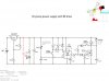
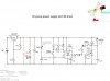
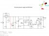
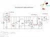
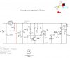
I am having a similar problem. I had false triggering on my timer setup then I added a 220 microF cap. across the 6V rail as someone suggested here and it worked (schematic attached). At the time I didn't have the manual switch installed. Now when I use the manual switch it sets off the timer. Boncuk shows a schematic that isolates the trigger (pin 2 of the 555 timer) with a transistor. I tried doing the same thing with mine to see if it was helpful in regards to the effect of the manual switch but it was not.

Thanks,

Jacques
 

Attachments

  • elec schematic timer  production modelt.jpg
    elec schematic timer production modelt.jpg
    597 KB · Views: 225
  • elec schematic timer  filling-mosfet-1.jpg
    elec schematic timer filling-mosfet-1.jpg
    609.6 KB · Views: 211
Last edited by a moderator:
Jacques,

Instead of a (relatively) high current switch to operate the pump motor, why not just provide a low-current (with series resistor) input to the MOSFET? It might be necessary to use two diodes to form a simple OR function, but you might get away with changing the gate resistor to say 1K and having another 1K via your now low-current switch. I think even 10K's would work, someone out there would know.
 
Thanks Aardy, I'm kind of a newbie at this. Is this what you mean? (see attached)
 

Attachments

  • elec schematic manual switch diode.jpg
    elec schematic manual switch diode.jpg
    597.2 KB · Views: 178
Wooops, I think I need to move the manual switch diode out ahead of the pin 3 diode.
 

Attachments

  • elec schematic manual switch diode.jpg
    elec schematic manual switch diode.jpg
    597.2 KB · Views: 154
aardyvarky, this works, unfortunately allot less power is getting to the motor. I can tell by the sound of the pump, and allot less flow is being produced. I am using a 700 ohm resistor ahead of the diodes because that is what I have.

Jacques
 
The switch can come directly from the V+ line, and, as a general rule, a protection diode should be reverse-biased across the LM317 (i.e. cathode on the input, anode on the output). Consider some small (0.1 microfarad) caps across i/p pin to gnd pin, and o/p pin to gnd pin of LM317 - see its datasheet. In fact, always check datasheets...
 
The switch can come directly from the V+ line, and, as a general rule, a protection diode should be reverse-biased across the LM317 (i.e. cathode on the input, anode on the output). Consider some small (0.1 microfarad) caps across i/p pin to gnd pin, and o/p pin to gnd pin of LM317 - see its datasheet. In fact, always check datasheets...

I'm not too sure what you mean by putting the switch on the V+ line, the motor is already connected to this line if I move the switch ahead of the motor it will not work with the timer.

I'm not 100% sure about the reverse bias diode on the LM317, I'm going to modify the schematic, let me know if you see something wrong.

I used to have a cap. as indicated on the data sheet across the 6V rail, I took it out because it didn't seem to help anything, I will put it back in.

I tried a 240 ohm resistor on the timer and man. switch diodes and power is improved on the pump. As it stands now the man. switch mostly works but sometimes it triggers the timer.
 

Attachments

  • elec schematic manual switch diode.jpg
    elec schematic manual switch diode.jpg
    597.8 KB · Views: 191
Your schematic does not show a part number for your Mosfet. If it is the original IRFZ30 then its datasheet shows that its gate needs 10V for it to fully turn on and some IRFZ30 Mosfets conduct only 0.25mA when the gate is only 4V. Your pump needs a much higher current.
With a 5V supply the datasheet of an ordinary 555 shows that its output goes as high as only 3.7V when it has almost no load. Way too low for most Mosfet gates.
On the LM317 you have a capacitor (which is wrong) in parallel with the 240 ohm resistor from the output to the ADJ pin but the datasheet has only the resistor or the resistor with an added parallel diode when the ADJ pin has a capacitor to ground.

Maybe your pump draws a huge current when it starts running that overloads the output of the LM317 then the +5V drops and triggers the 555?
 
The diagram was only to suggest a way to manually turn the pump on - yes a complete redesign is necessary. Perhaps a bipolar transistor would be better? To be honest, the LM317 isn't really needed, it could be run directly off the battery. Keep it simple and cheaper!
 
Somewhere it says the motor is a 6V motor so maybe 9V is too much for it. Nowhere says the size of the 9V battery. Is a little 9V battery able to produce enough power to drive the motor? Maybe the little 9V battery "falls on its face" when the high starting current of the motor causes its voltage to drop which causes a false trigger of the 555?
 
Both the schematics in the 1st post of this thread show a 9v battery, but I will wait until jacbk6121 replies - at least we are not wasting our time. I've read so many threads where the original OP (is OP right?) seems to just disappear.
And yes, we need to know the spec of the pump motor...
 
I've read so many threads where the original OP (is OP right?) seems to just disappear.

OP is commonly used around here in the forum.
OP = Original Poster

And yes, many do disappear or never acknowledge replies to their posts.
By that I do not mean that Jacbk6121 will be one of them.

JimB
 
Your schematic does not show a part number for your Mosfet. If it is the original IRFZ30 then its datasheet shows that its gate needs 10V for it to fully turn on and some IRFZ30 Mosfets conduct only 0.25mA when the gate is only 4V. Your pump needs a much higher current.
With a 5V supply the datasheet of an ordinary 555 shows that its output goes as high as only 3.7V when it has almost no load. Way too low for most Mosfet gates.
On the LM317 you have a capacitor (which is wrong) in parallel with the 240 ohm resistor from the output to the ADJ pin but the datasheet has only the resistor or the resistor with an added parallel diode when the ADJ pin has a capacitor to ground.

Maybe your pump draws a huge current when it starts running that overloads the output of the LM317 then the +5V drops and triggers the 555?
Thanks for the comments.
Yes I am using the IRFZ30 mosfet.
Regarding the LM317 I am using the recommended hookup from the datasheet except the cap. across pin 2 is a 220 microF instead of a 1 microF shown on the datasheet. The 220 cap. is what makes the trigger work, before that the timer would not work at all.
 

Attachments

  • LM317TG.pdf
    146.9 KB · Views: 132
The diagram was only to suggest a way to manually turn the pump on - yes a complete redesign is necessary. Perhaps a bipolar transistor would be better? To be honest, the LM317 isn't really needed, it could be run directly off the battery. Keep it simple and cheaper!

There are no specs on the pump, all I know is that it will work with a 3-6V power supply.
I have had many versions of this system before I got the timer to work at all. One was with a relay, then a transistor (NPN PN2222A) and now a mosfet IRFZ30 on 555 timer pin 3.
Keep it simple is great, the less parts the better, I don't have allot of space to put the PCB.
There are 2 remaining problems:
1. Timer triggers on power up;
2. Manual switch triggers timer.

I am using the mall regular rectangular 9V battery , not sure what the format name is. I get 200 fill cycles with it.
 
Somewhere it says the motor is a 6V motor so maybe 9V is too much for it. Nowhere says the size of the 9V battery. Is a little 9V battery able to produce enough power to drive the motor? Maybe the little 9V battery "falls on its face" when the high starting current of the motor causes its voltage to drop which causes a false trigger of the 555?
The 9V works fine, E style, 200 cycles.
 
OP is commonly used around here in the forum.
OP = Original Poster

And yes, many do disappear or never acknowledge replies to their posts.
By that I do not mean that Jacbk6121 will be one of them.

JimB
I certainly will not, I appreciate all the help I can get. I'm not an electro-tech guy but a mechanical engineer, way over my head.
 
I certainly will not, I appreciate all the help I can get. I'm not an electro-tech guy but a mechanical engineer, way over my head.
Welcome to ETO.
JimB
 
Thanks for the schematic. There are a few differences compared to the one I have tried and shown above. Some caps. around the LM317 pin 1 and a cap. on the motor leads which I have done differently. I will give this a shot.
I have tried these modifications ( see attached) and no success. I don't have any 0.1 microF so I am using the 0.01, I will go to the store to get some 0.1's and try again. I did the changes sequentially.
 

Attachments

  • elec schematic manual switch diode.jpg
    elec schematic manual switch diode.jpg
    608.1 KB · Views: 181
Status
Not open for further replies.

Latest threads

New Articles From Microcontroller Tips

Back
Top