Continue to Site

Welcome to our site!

Electro Tech is an online community (with over 170,000 members) who enjoy talking about and building electronic circuits, projects and gadgets. To participate you need to register. Registration is free. Click here to register now.

  • Welcome to our site! Electro Tech is an online community (with over 170,000 members) who enjoy talking about and building electronic circuits, projects and gadgets. To participate you need to register. Registration is free. Click here to register now.

Making a timer on delay and off delay without microcontroller

fadlianturu6

New Member
I am new and want to make a compact circuit without a microcontroller. The idea is when you push the button/switch, it will delay the timer for at least 6 hours. After that, it will activate the motor for 20 seconds and loop forever. I am thinking of using a 555 timer with a 1000uF capacitor here, but it fails miserably. Any ideas?
Screenshot_227.png
 
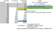
Let T1 = 21,600 s min
T2= 20 s approx.
T1/T2 =1080 is close to 1024 or 2^10

Now check out the CD4060 and make a clock with Qn and Qn+10 match your time intervals.

1708483400363.png


Then buffer with a motor driver IC.

CD4xxx series can only drive 10K or so depending on Vdd voltage.

The 74HCT4060 can drive < 1kohm with ~ <50 Ohm driver @ Vdd=5.5V max.
https://www.digikey.ca/en/products/detail/texas-instruments/SN74HC4060N/386620

 
Last edited:
Let T1 = 21,600 s min
T2= 20 s approx.
T1/T2 =1080 is close to 1024 or 2^10

Now check out the CD4060 and make a clock with Qn and Qn+10 match your time intervals.

View attachment 144583

Then buffer with a motor driver IC.

CD4xxx series can only drive 10K or so depending on Vdd voltage.

The 74HCT4060 can drive < 1kohm with ~ <50 Ohm driver @ Vdd=5.5V max.
https://www.digikey.ca/en/products/detail/texas-instruments/SN74HC4060N/386620

what is Qn ? and can you looping it ?
 
Use a CD4060.

Look at the TI.com version of the datasheet. Use a 10uF ceramic capacitor with a 91k ohm resistor for timing circuit Cx and Rx (see Fig 12 on the datasheet). This will give you 20-second pulses.

Use a 3-input AND gate and connect three inputs the CD4060's pins 15, 5 and 7 to get very close to 6 hours. The output of this AND gate to a MOSFET that drives a motor.

Then connect pins 4 and 15 on the CD4060 to the inputs of an AND gate (output from that AND gate to the reset pin of the CD4060).


*********
Also, the Q divider outputs on Tony Stewart image of the CD4060 doesn't align with the datasheet.

1708485411503.png
 
what is Qn ? and can you looping it ?
The 4060 from website who shall go nameless uses Q3 to Q13 which is wrong label but follows binary convention from Q0,Q1,Q2 etc.

While the original datasheet uses Q4 to Q14 to match powers of 2 for divider starting from Q1,Q2,Q3 ....

But the pins match functions in both IC's CD4060 and 74HC4060

while the 74HC4060 which has a lower driver impedance uses letters QD to QN even worse but avoids the embarassing correction to binary addresses.


1708494312283.png
 
Last edited:
I posted a concept circuit to do a very similar thing just last night, here:


If C3 was eg. 10uF and VR1 adjusted to give a ~ 5.3 second oscillator cycle, that should give a delay of around six hours before Q14 goes high and triggers the output.

Changing C4 to eg. 47uF should give an output pulse duration adjustable (with VR2) to 20 seconds.

Use the "solenoid" output connections to control a relay to switch the motor power, or change Q2 to a PNP power darlington, with high enough current rating for the motor and a suitable heatsink.
 
I have already built my prototype in Proteus using the IC 4060, and it runs perfectly. However, the results of the equations are not exactly matching the values stated in the datasheet. Could you help me identify what revisions I should make? Additionally, could you recommend a book for beginners on wiring circuits like this?
Screenshot_228.png

f C3 was eg. 10uF and VR1 adjusted to give a ~ 5.3 second oscillator cycle, that should give a delay of around six hours before Q14 goes high and triggers the output.
yeah but idk why in datasheet and here the equation is very different its like 1-3k ohm.
Look at the TI.com version of the datasheet. Use a 10uF ceramic capacitor with a 91k ohm resistor for timing circuit Cx and Rx (see Fig 12 on the datasheet). This will give you 20-second pulses.

Use a 3-input AND gate and connect three inputs the CD4060's pins 15, 5 and 7 to get very close to 6 hours. The output of this AND gate to a MOSFET that drives a motor.
Thank you very much for you all.
 

Attachments

  • Roller3.rar
    15.7 KB · Views: 167
Your original circuit would never work with that large 1000uf cap as its rate of charge is not greater than its internal loss.

When trying to produce a long timing period with whatever ic and an electrolytic capactitor you should use the smallest value one, even if it means more dividing stages. The smaller the value the less internal loss and so better timing.

Even with small values eg 1 uf - 100 uf you should ideally use Tantalum capactiors which have little internal loss and so better timings.
eg - https://uk.rs-online.com/web/c/?searchTerm=100uf+tantalum

For wiring your circuits, do you have any soldering equipment ?
You can use a solderless breadboard but for timing circuits they can cause their own problems, so better to solder or wire wrap your circuit.
 
You said you wanted minimum parts and accurate timing. If you are
new to programming then block language programming quite simple
and straight forward.

The ATTINY85 8 pin micro can do this in one part (plus bypass cap for it and
a regulator), code it with mBlock. mBlock takes your block configuration, shown
in right hand window, and converts that to Arduino code. Note in addition to the
part you of course need interface switch for motor power......

I think this example would be a good basis for design. Question, what causes loop
to stop, powering off whole system ?

1708519905061.png


You program the ATTINY85 with a Nano board configured as a programmer, thats
just a firmware you burn into Nano board. Nano board ~ $3. Note if you use Nano
Board as target its timing error < .1% as it has a xtal on board. If you use ATTINY85
as target its timing tolerance is ~ +/- 1% over T and V.

So if design is a one off, use the board, simple. Otherwise config board as programmer,
easy with Arduino IDE, videos on this, and use the ATTINY85.

Just a thought.....


Regards, Dana.
 
Last edited:
You said you wanted minimum parts and accurate timing. If you are
new to programming then block language programming quite simple
and straight forward.

The ATTINY85 8 pin micro can do this in one part (plus bypass cap for it and
a regulator), code it with mBlock. mBlock takes your block configuration, shown
in right hand window, and converts that to Arduino code. Note in addition to the
part you of course need interface switch for motor power......

I think this example would be a good basis for design. Question, what causes loop
to stop, powering off whole system ?

View attachment 144593

You program the ATTINY85 with a Nano board configured as a programmer, thats
just a firmware you burn into Nano board. Nano board ~ $3. Note if you use Nano
Board as target its timing error < .1% as its has a xtal on board. If you use ATTINY85
as target its timing tolerance is ~ +/- 1% over T and V.

So if design is a one off, use the board, simple. Otherwise config board as programmer,
easy with Arduino IDE, videos on this, and use the ATTINY85.

Just a thought.....


Regards, Dana.
Thank you for your thoughts. I understand that it's very easy if we use microcontrollers like Arduino, etc., but I want to learn more basics. I want to understand each part of electronics separately. I know it may sound inefficient. T-T
 
6 hours is 21,600 seconds. Divide this by 20 seconds, and you get 1080. That means that if you have a clock circuit such that 1 tick is 20 seconds long, the overall timing period is 1080 ticks. This is very close to 1024, and raises questions.

1024 ticks is a nice round binary number that the CD4060 or many other binary counters can handle easily without messy output gating, If we stick with a 20-second tick, the overall period would be 5 hours 41 minutes. Is this acceptable?

Alternatively, if we hold the overall period to exactly 6 hours, then for a 1024-tick period, one tick is 21.094 seconds. Is this acceptable?

A yes to either of these options means you can do this with one CD4060 *and no 555 timer*.

ak
 
1708498076681.png How did you compute T ? there are reasons at really slow clocks this is inaccurate.

It is like a flashback to 1976 with all these 4060 solutions, assumptions and things overlooked in accuracy.

Above is the original formula for one period, T of a clock cycle.
Using 10 uF electrolytic capacitors will experience reverse voltage (not accurate) since the average voltage differential is not zero. The clock R-RC junction average for Vcc=12 will be 24Vpp and will be offset from Vcc/2 will be the inversion of the input offset threshold roughly..

- the ϕO input with/without ESD protection, and output is shown below
Thank you for your thoughts. I understand that it's very easy if we use microcontrollers like Arduino, etc., but I want to learn more basics. I want to understand each part of electronics separately. I know it may sound inefficient. T-T
Remember this. All logic is basically clipped analog signals with RC and diode effects.

What accuracy do you expect? It won't cycle at the same time each day. How will you know it is accurate?
How will you know other than to measure every 6 hrs? ...in case of unexpected disturbances.
Be sure to have fault detection in any design. e.g. timing checks like a slow pulse LED to check quickly.

What can cause disturbances in counting analog bi-exponential clipped waves to some threshold with a wide tolerance.

If it were not for the internal ESD protection diodes the input would be 2*Vcc= 24Vpp

Things to remember using the 74HC/CD/4060:
  1. This CMOS IC has threshold tolerances like all CMOS and the RC timing here is not linear, rather it is the sum of two exponents clipped by ESD protection and switches with some variable offset to Vcc/2 +/- xx % at room temp then varies with temp.
What errors did you measure, expect and use to calculate the period T?

When taken to extremes, electrolytic capacitors leak with an equivalent resistance of Vtest/Ileak=Rp and each e-cap family has different Rp*C=Tau time constants and varies with temperature and quality specs. A small e-cap might have Tau = 10 seconds. This can increase with bulk size of C and quality.

Electrolytics leak far more in reverse voltage and fortunately this is current limited otherwise it might explode. So beware using e-caps for timing errors in this circuit. Although I simulated an ideal cap.

These may also apply to some modern uC that use RC external slow clocks.
  1. See the actual input to the 10xR inverter input below assuming Vcc = 12V on CD4060. (Red plot=24Vpp)
  2. If you do not report what you used, calculated and measured, then we have no error to correct.
  3. Remember this is a ripple counter so latency and rise time with different thresholds may cause gating multiple outputs to have glitches during transitions as the latency accumulates after each ripple /2 count.
  4. If you use another matching 10*R input to Vcc the 2*Vcc_pk-pk would be reduced in half and no long have in the internal clipped ugly waveform ( that you cannot measure accurately because the low current (5mA) Schottky diodes must have 50 K current limiting R's in front to survive the kV ESD tests. Then there must be 2 stages to ensure no shootthru.
  5. 1708536791319.png
 
Last edited:
Bravo to rjenkinsgb for choosing a single output on the ripple counter and avoiding race conditions on gated outputs on an asynchronous "Ripple Counter"

Bravo to danadak for teaching us "old dogs" new tricks ... even though some of us have mblock to coding with new tools........."memory block" (pun intended)
 
View attachment 144587 How did you compute T ? there are reasons at really slow clocks this is inaccurate.

It is like a flashback to 1976 with all these 4060 solutions, assumptions and things overlooked in accuracy.

Above is the original formula for one period, T of a clock cycle.
Using 10 uF electrolytic capacitors will experience reverse voltage (not accurate) since the average voltage differential is not zero. The clock R-RC junction average for Vcc=12 will be 24Vpp and will be offset from Vcc/2 will be the inversion of the input offset threshold roughly..

- the ϕO input with/without ESD protection, and output is shown below

Remember this. All logic is basically clipped analog signals with RC and diode effects.

What accuracy do you expect? It won't cycle at the same time each day. How will you know it is accurate?
How will you know other than to measure every 6 hrs? ...in case of unexpected disturbances.
Be sure to have fault detection in any design. e.g. timing checks like a slow pulse LED to check quickly.

What can cause disturbances in counting analog bi-exponential clipped waves to some threshold with a wide tolerance.

If it were not for the internal ESD protection diodes the input would be 2*Vcc= 24Vpp

Things to remember using the 74HC/CD/4060:
  1. This CMOS IC has threshold tolerances like all CMOS and the RC timing here is not linear, rather it is the sum of two exponents clipped by ESD protection and switches with some variable offset to Vcc/2 +/- xx % at room temp then varies with temp.
What errors did you measure, expect and use to calculate the period T?

When taken to extremes, electrolytic capacitors leak with an equivalent resistance of Vtest/Ileak=Rp and each e-cap family has different Rp*C=Tau time constants and varies with temperature and quality specs. A small e-cap might have Tau = 10 seconds. This can increase with bulk size of C and quality.

Electrolytics leak far more in reverse voltage and fortunately this is current limited otherwise it might explode. So beware using e-caps for timing errors in this circuit. Although I simulated an ideal cap.

These may also apply to some modern uC that use RC external slow clocks.
  1. See the actual input to the 10xR inverter input below assuming Vcc = 12V on CD4060. (Red plot=24Vpp)
  2. If you do not report what you used, calculated and measured, then we have no error to correct.
  3. Remember this is a ripple counter so latency and rise time with different thresholds may cause gating multiple outputs to have glitches during transitions as the latency accumulates after each ripple /2 count.
  4. If you use another matching 10*R input to Vcc the 2*Vcc_pk-pk would be reduced in half and no long have in the internal clipped ugly waveform ( that you cannot measure accurately because the low current (5mA) Schottky diodes must have 50 K current limiting R's in front to survive the kV ESD tests. Then there must be 2 stages to ensure no shootthru.
  5. View attachment 144596
So where should i start first ?
and for calculate i just calculate with datasheet
1708569346441.png

and the times i need for nearly 6 hours
1708569396946.png

Are there any book recommendations for something like this? Because I almost don't know half of it.
 
Last edited:
All the old national books are in archive.org including tons of design books and Bob Pease stuff
 
Start with what you know or need to learn. This is 50 yr old technology.
So where should i start first ?
Draw a timing diagram or State Diagram and work out the logic
I chose last Qout to Reset counter for 6 hours. and also clock a 1 into FF to turn ON machine.
I then chose time intervals match 6 hrs rather than 20s as 21s is close enough.
Then computing backwards for next rising edge after 21 seconds to Reset FF to turn OFF machine

1708588372115.png


1708589069703.png
 

Attachments

  • 1708588829165.png
    1708588829165.png
    169.1 KB · Views: 154
Last edited:

Latest threads

New Articles From Microcontroller Tips

Back
Top