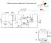
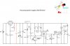
I would do it something like this.

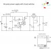
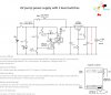
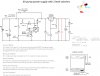
I would recomend runing this circuit straight from the battery and putting the regulator between this switching circuit and the motor. That way you will not have the cuurent taken by the regulator draining the battery all of the time. Almost any logic level N channel mosfet should work.
Les.
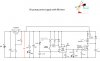
I would recomend runing this circuit straight from the battery and putting the regulator between this switching circuit and the motor. That way you will not have the cuurent taken by the regulator draining the battery all of the time. Almost any logic level N channel mosfet should work.
Les.